 by
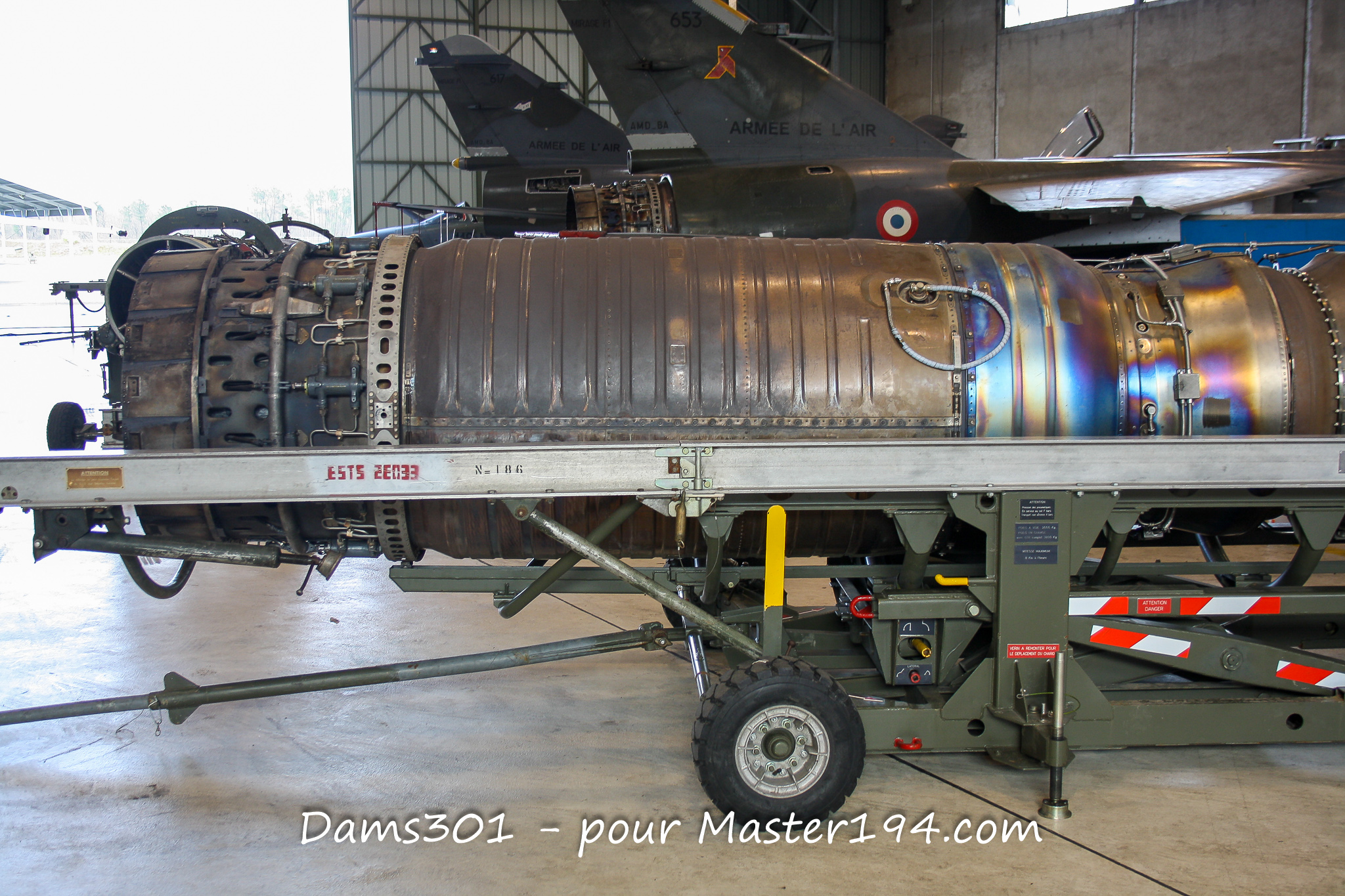
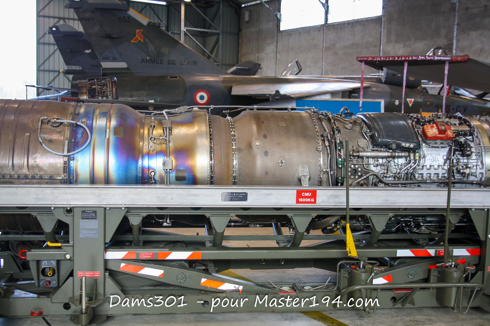
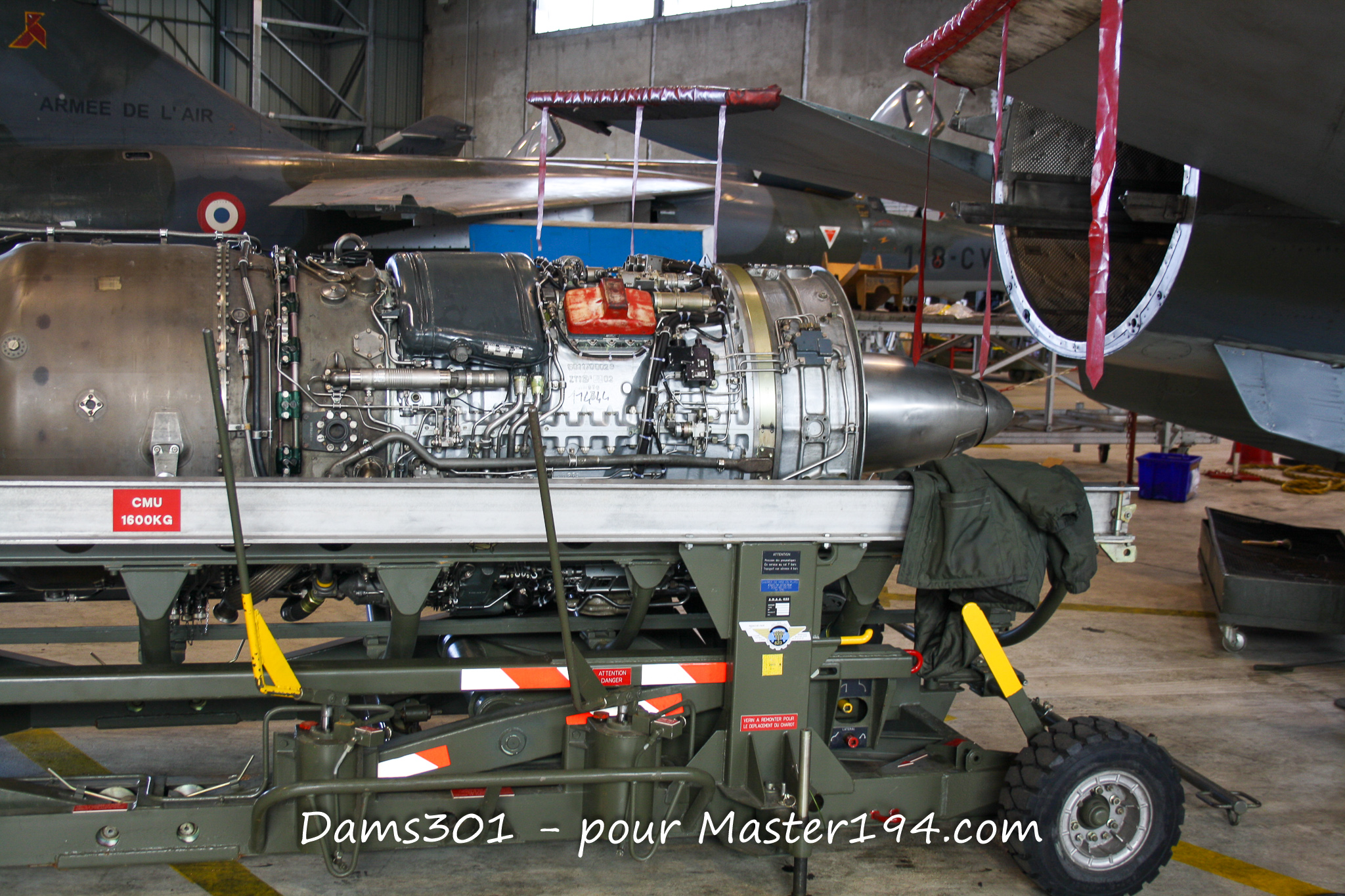
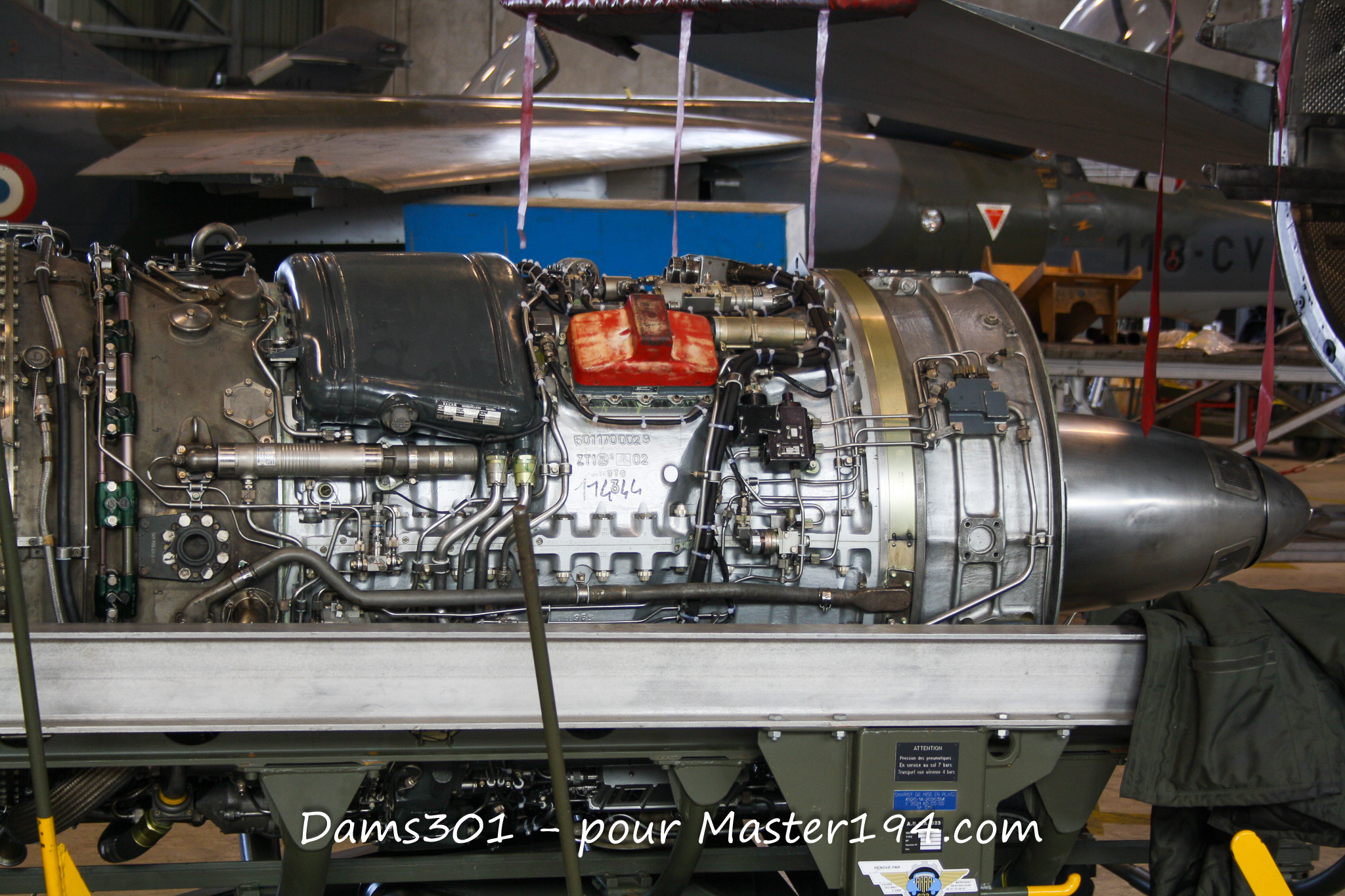
The Mirage F1 is inseparable from its engine. Unlike the Mirage III and Mirage 5, which relied on a delta wing design, Dassault’s new fighter adopted a swept wing to combine strong supersonic performance with significantly lower approach speeds. To power this new aircraft, SNECMA developed a major evolution of its famous ATAR turbojet family: the ATAR 9K50.
As the final major iteration of the ATAR family to equip a French fighter, this engine delivers up to 7,200 kgp (70.6 kN) with afterburner, while maintaining a relatively simple and robust architecture. It allowed the Mirage F1 to reach Mach 2.2.
All pictures taken by Dams301, thank you !
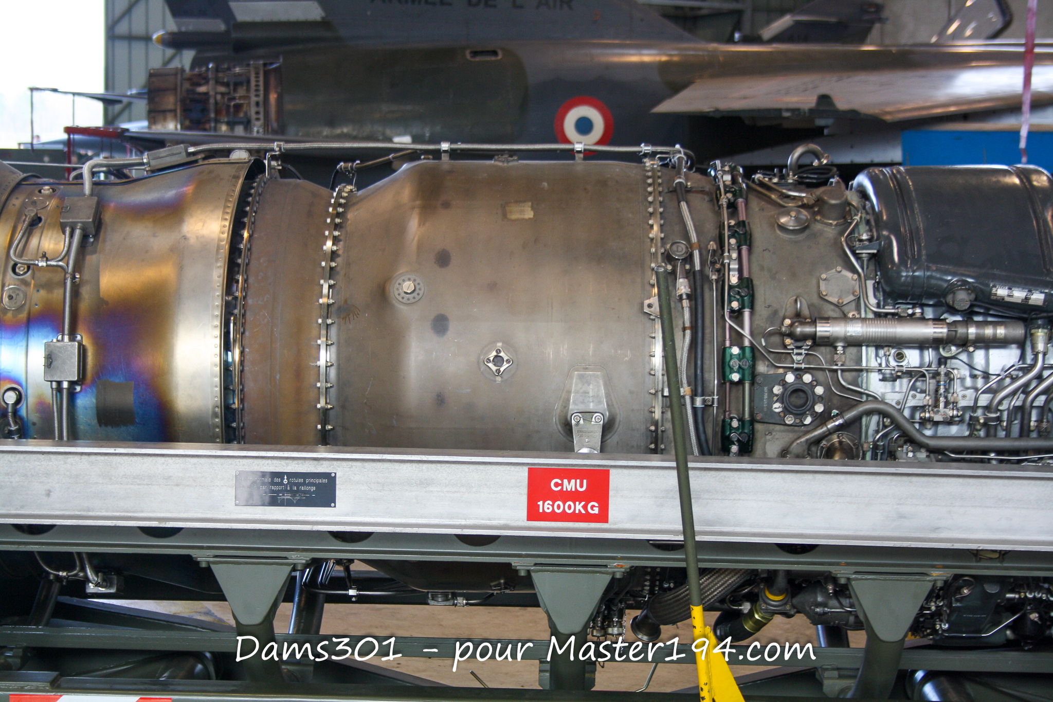
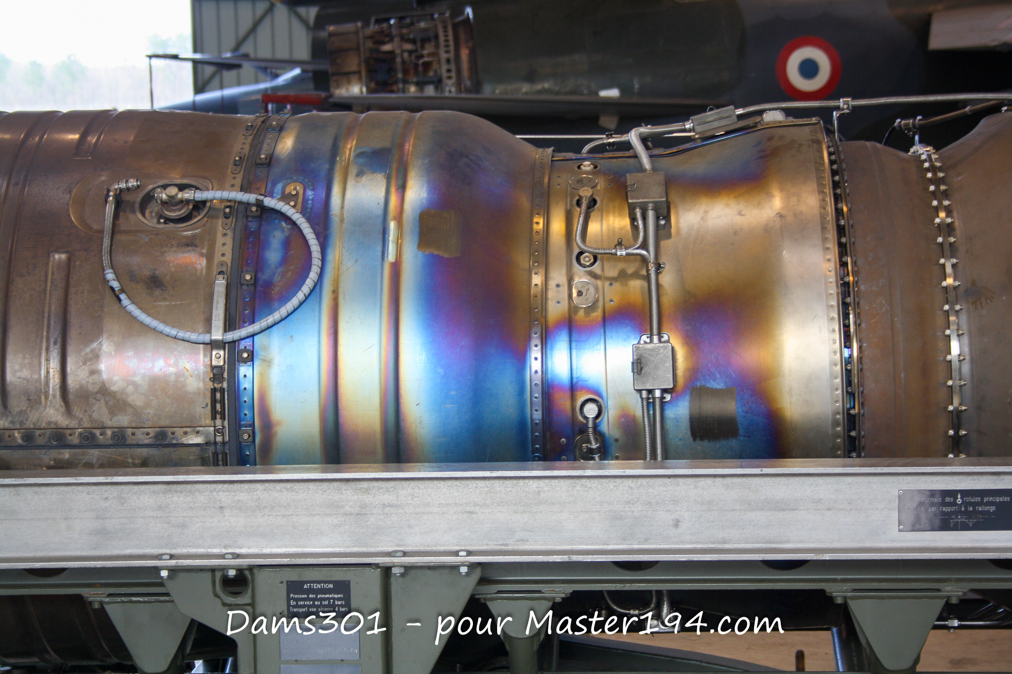
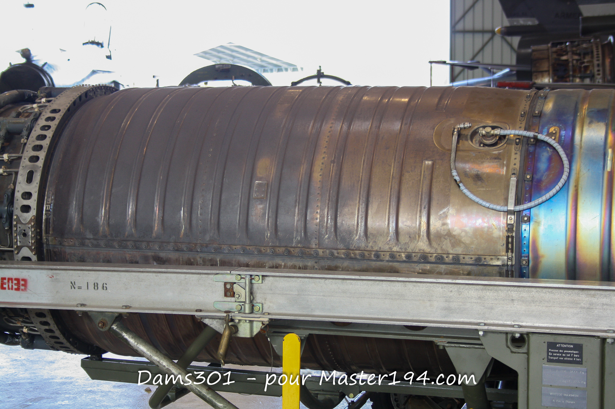
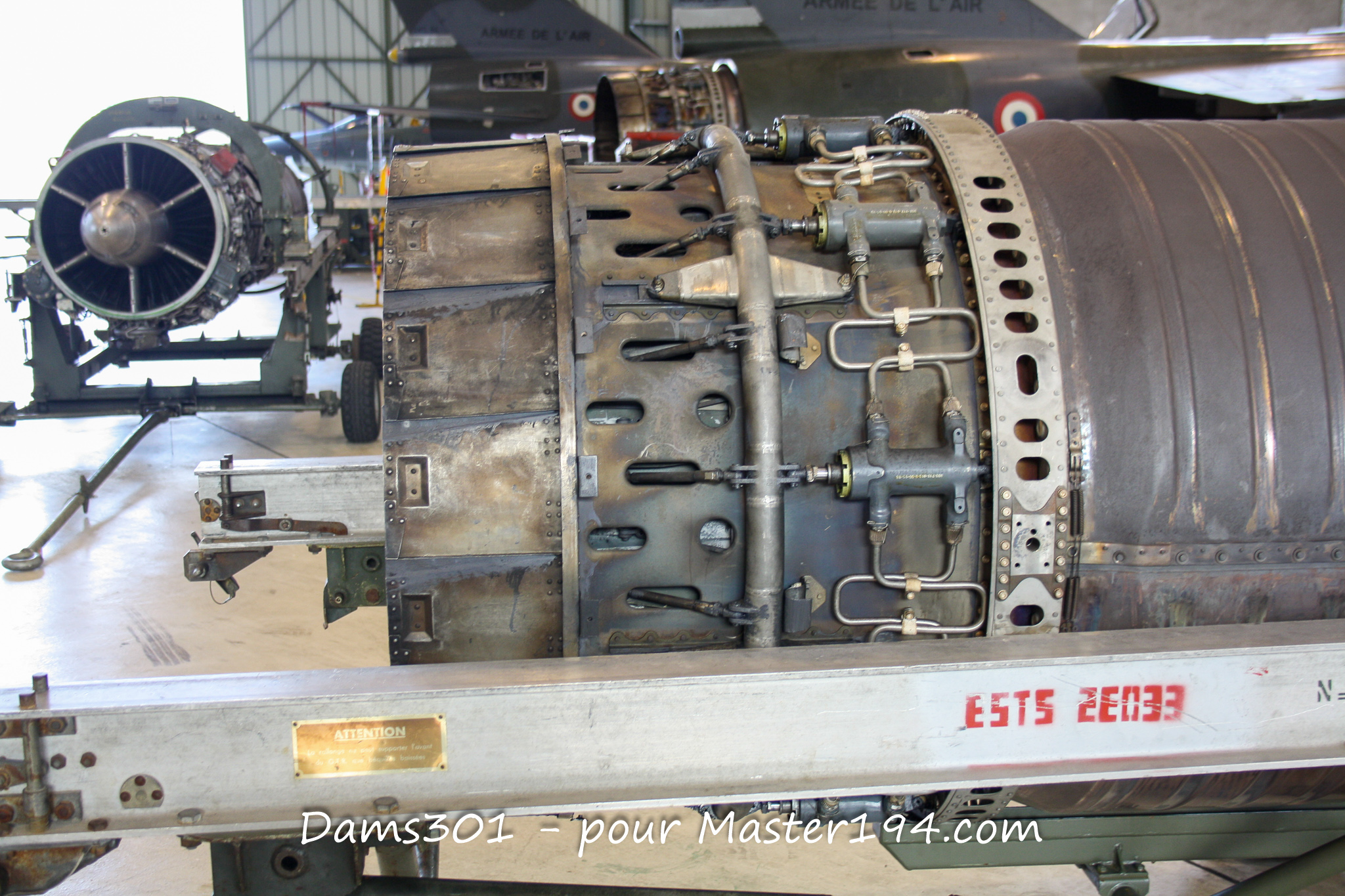
A Long Heritage
The history of the ATAR engine began in the immediate post-war era with the work of a team of German engineers led by Hermann Oestrich, who relocated to France after 1945. The name ATAR originates from “Atelier Technique Aéronautique de Rickenbach,” the design bureau behind this engine family.
Over the years, SNECMA evolved the powerplant through numerous variants. The ATAR 9B and 9C powered different versions of the Mirage III and Mirage 5, while the ATAR 9K was developed for the Mirage IV strategic bomber.
The ATAR 9K50 represents a particularly significant step forward. Studies began in 1967, the first bench test took place in February 1968, and flight testing started on a Mirage III testbed. The engine was certified in 1969, with serial production commencing in 1972.
The prototype Mirage F1 01 originally made its maiden flight on December 23, 1966, equipped with an ATAR 9K. Subsequent development aircraft were quickly retrofitted with the ATAR 9K50, which became the production standard. The first production-standard Mirage F1 C flew on February 15, 1973, prior to initial deliveries to the French Air Force in March 1974.
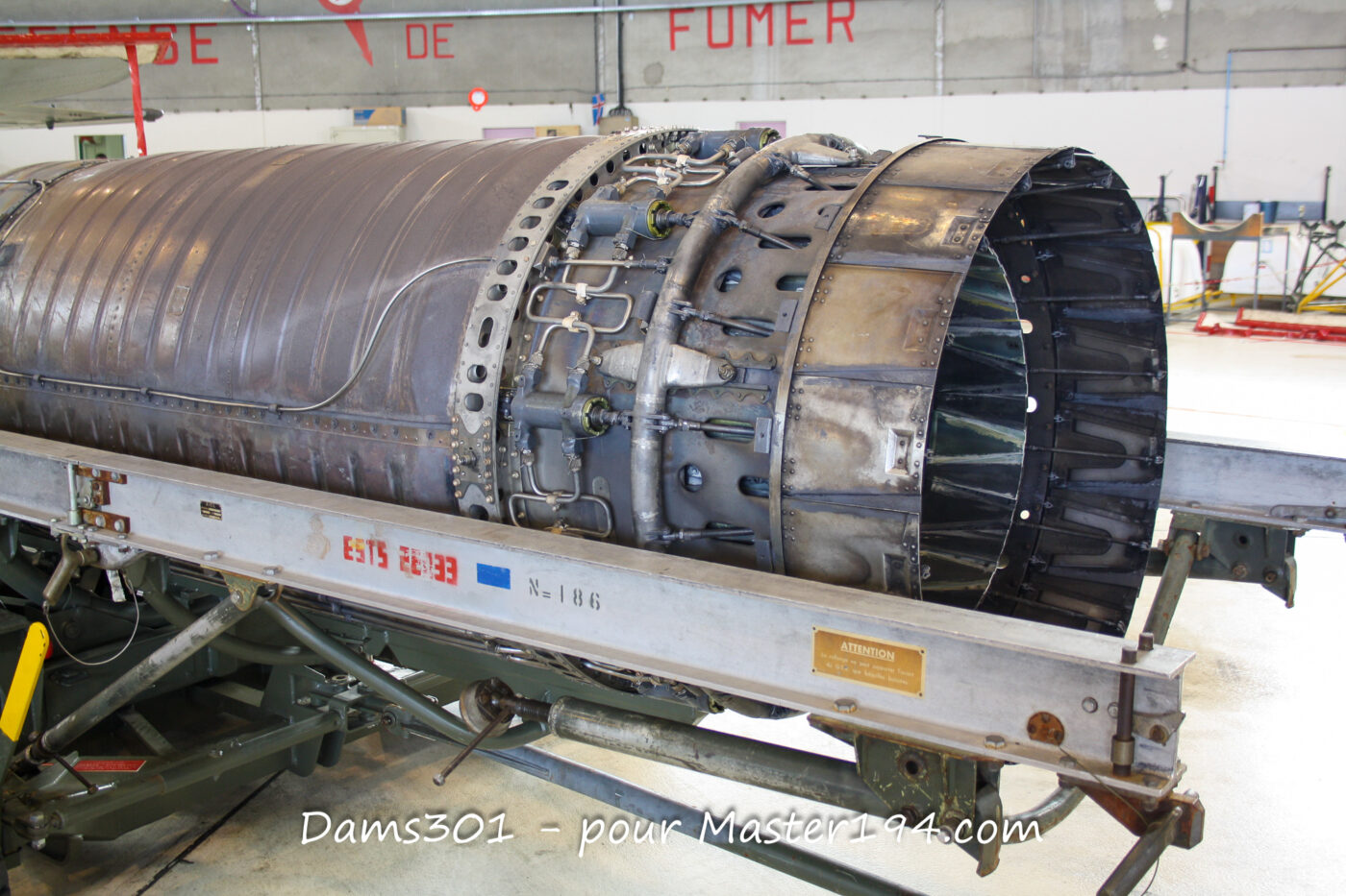
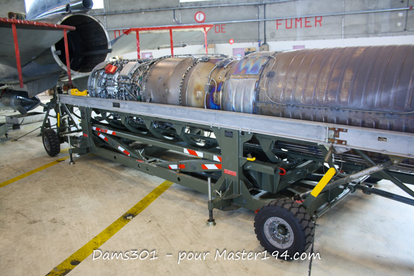
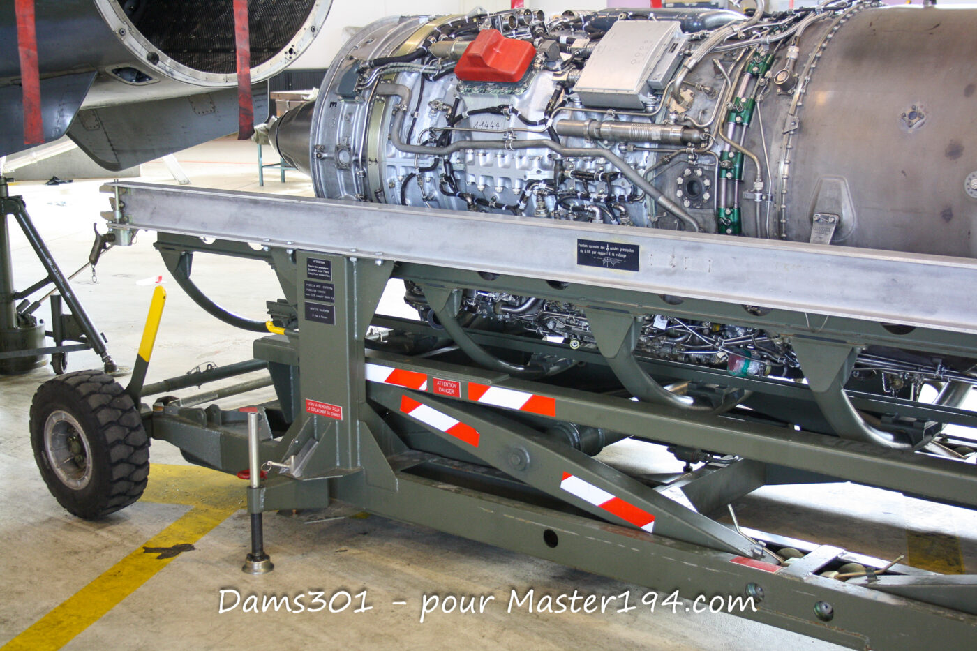
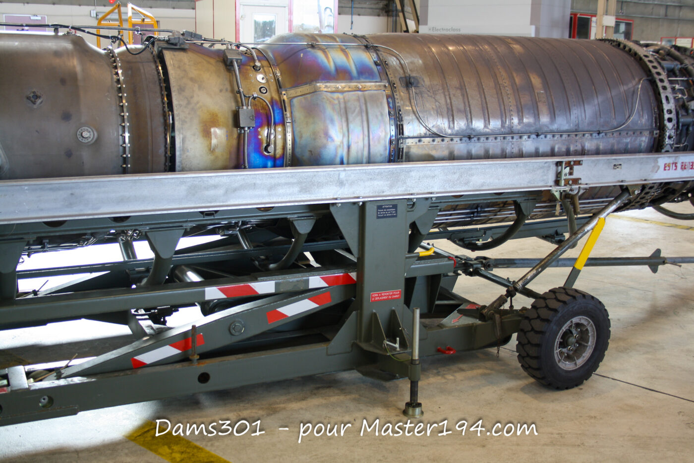
Single-Spool, Single-Flow Turbojet Architecture
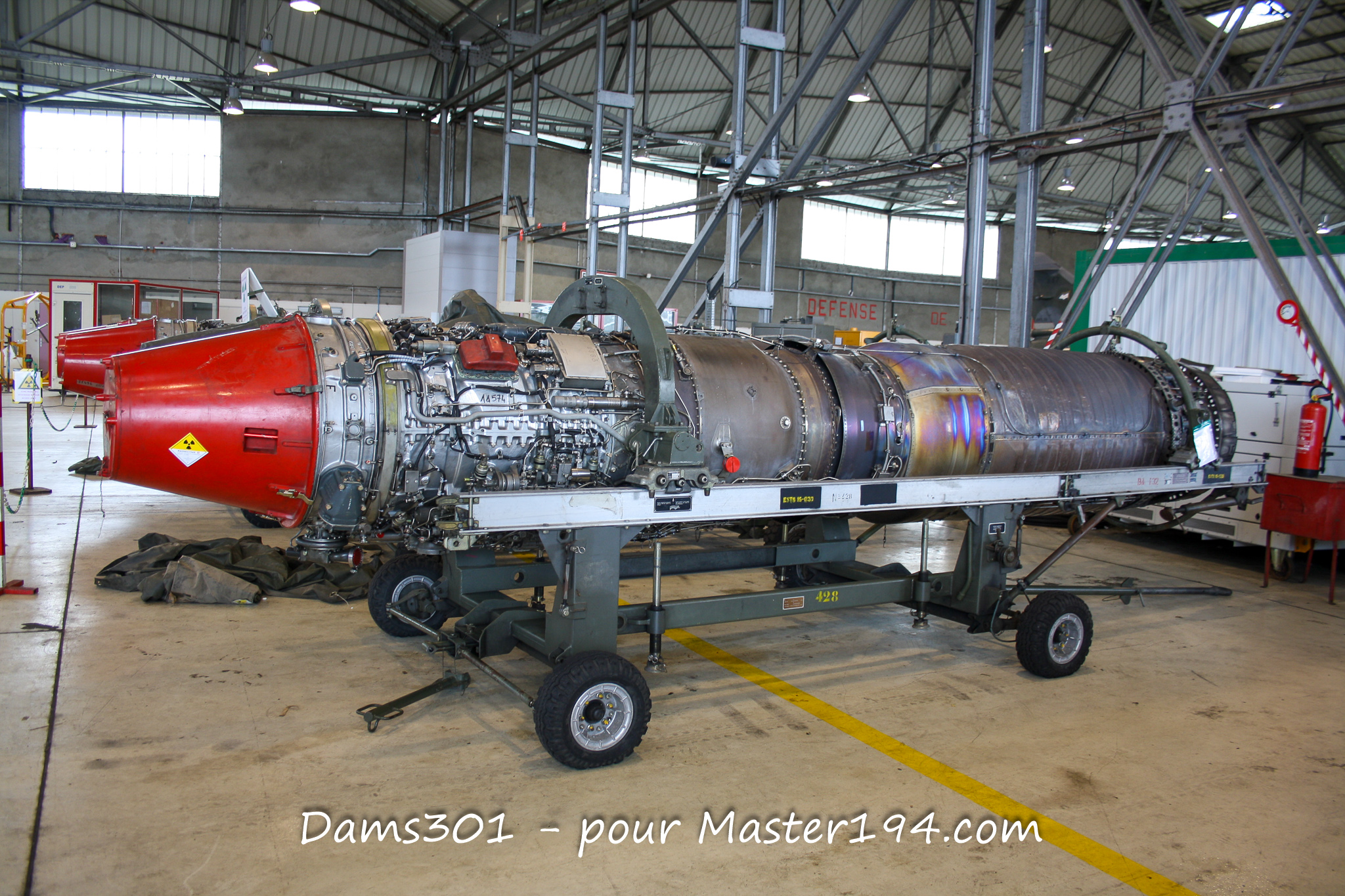
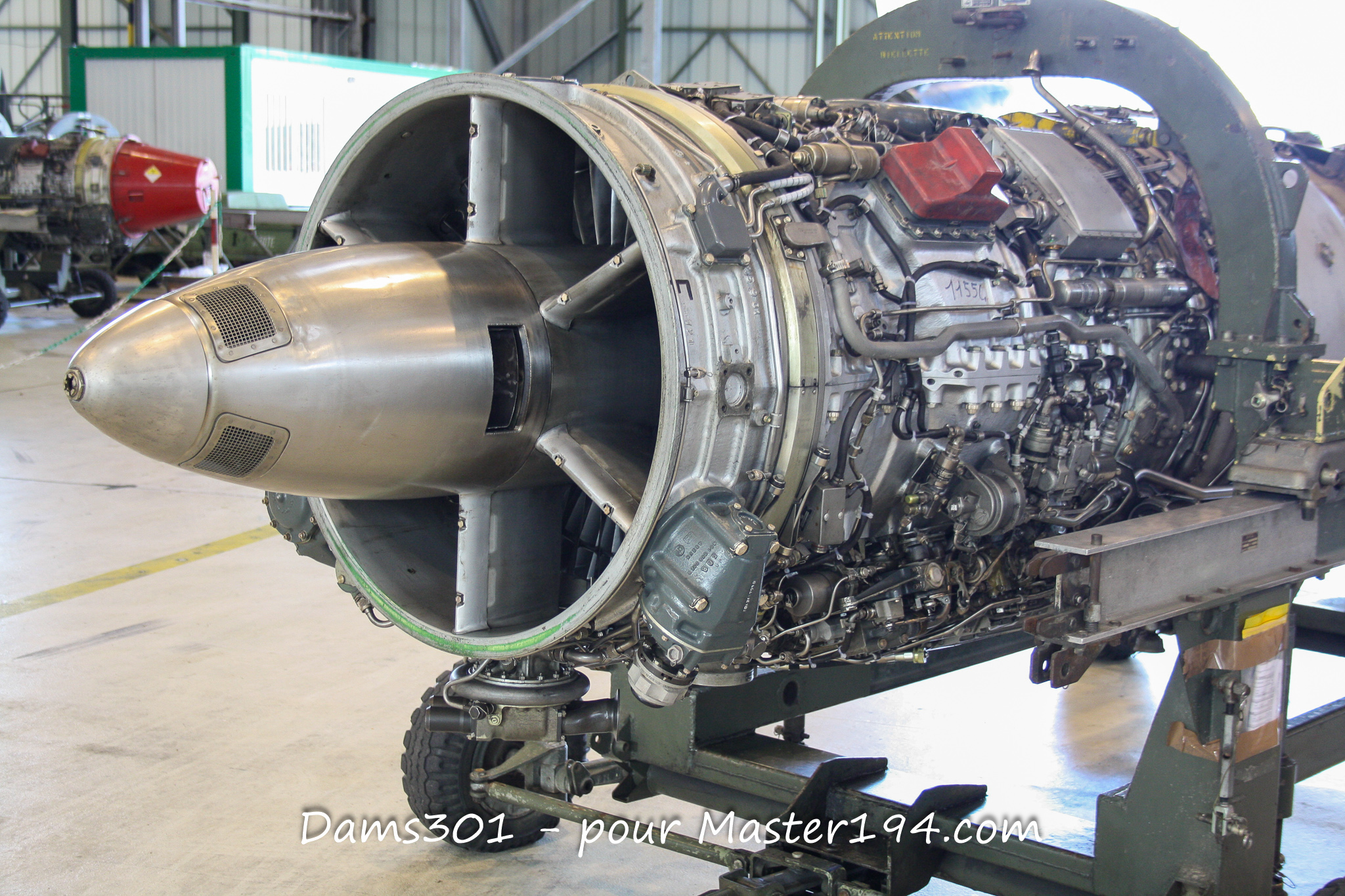
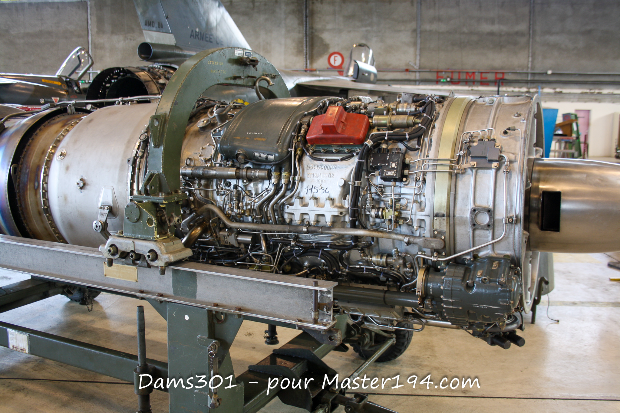
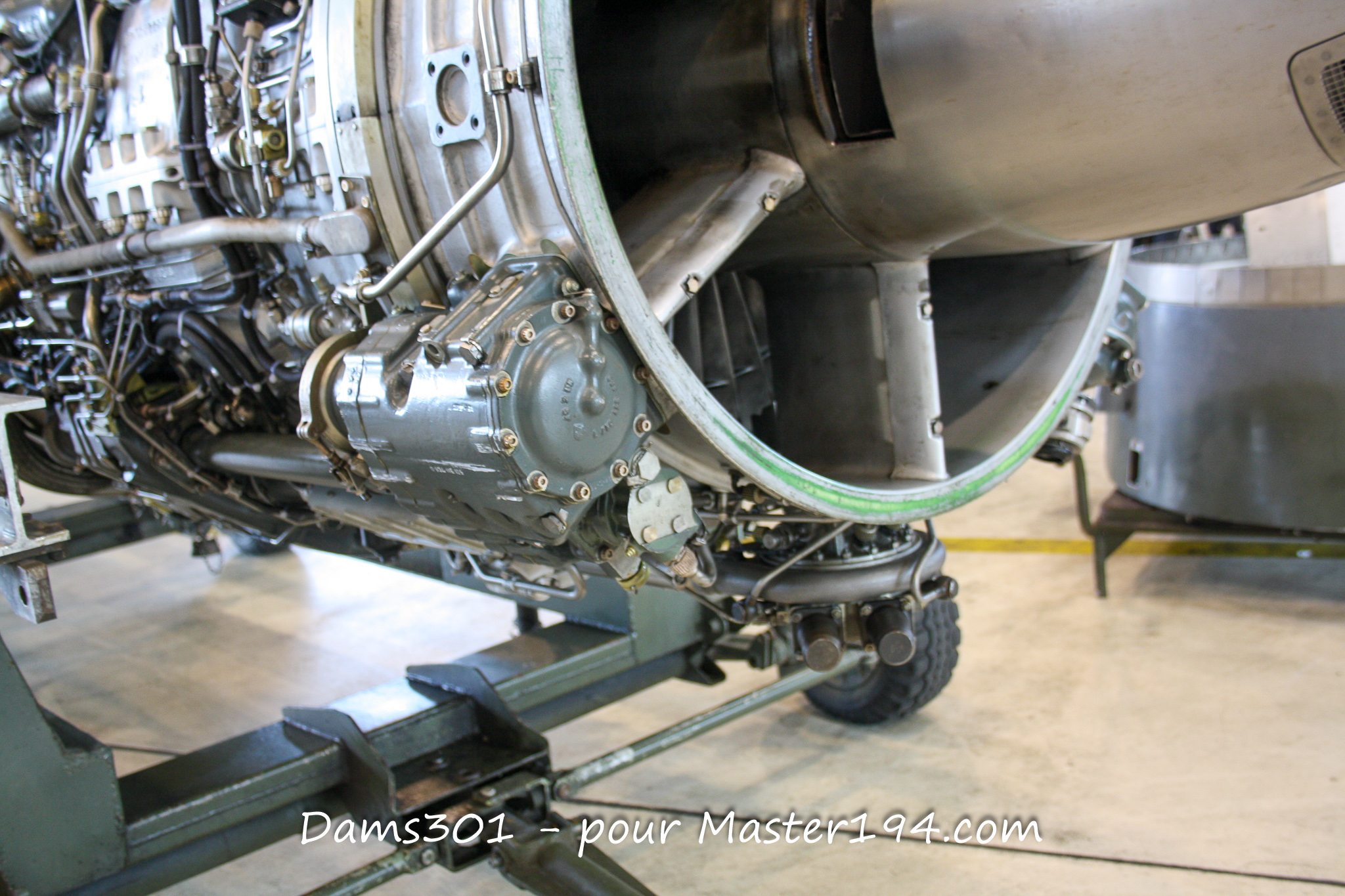
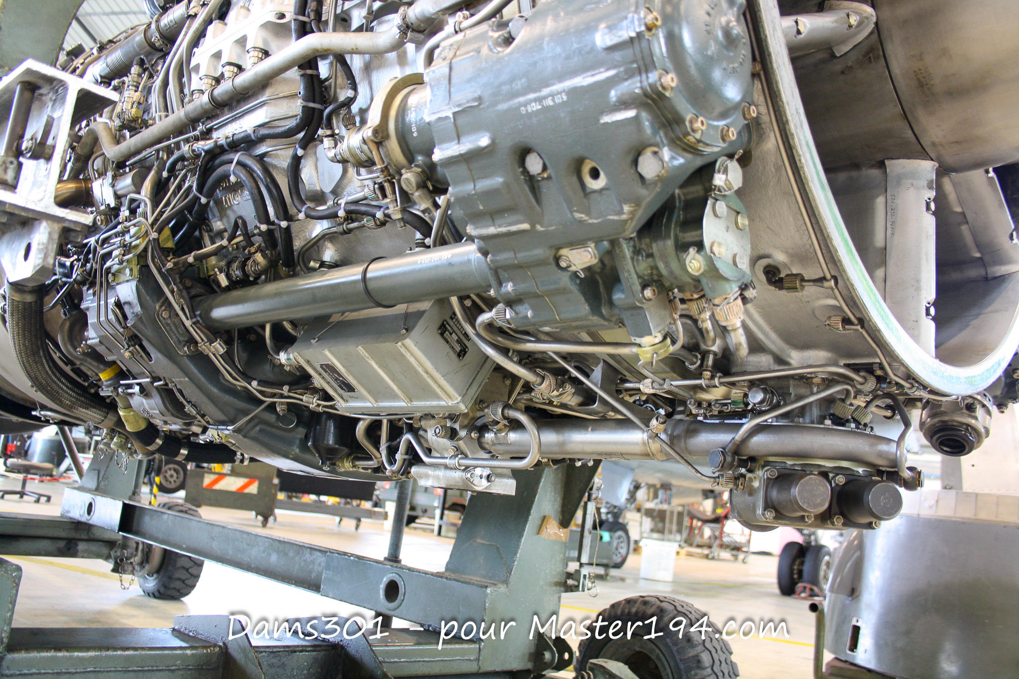
The ATAR 9K50 is an axial-flow, single-spool, single-flow (turbojet) engine equipped with an afterburner.
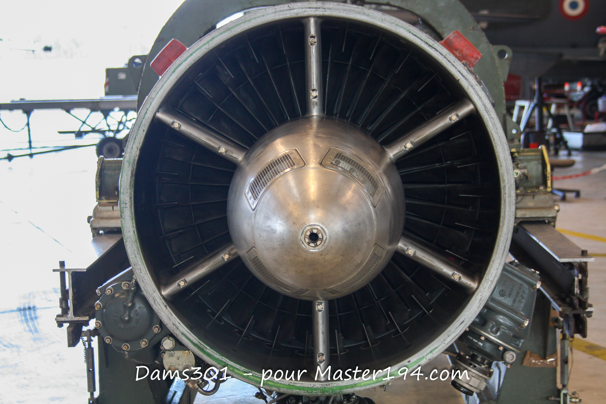
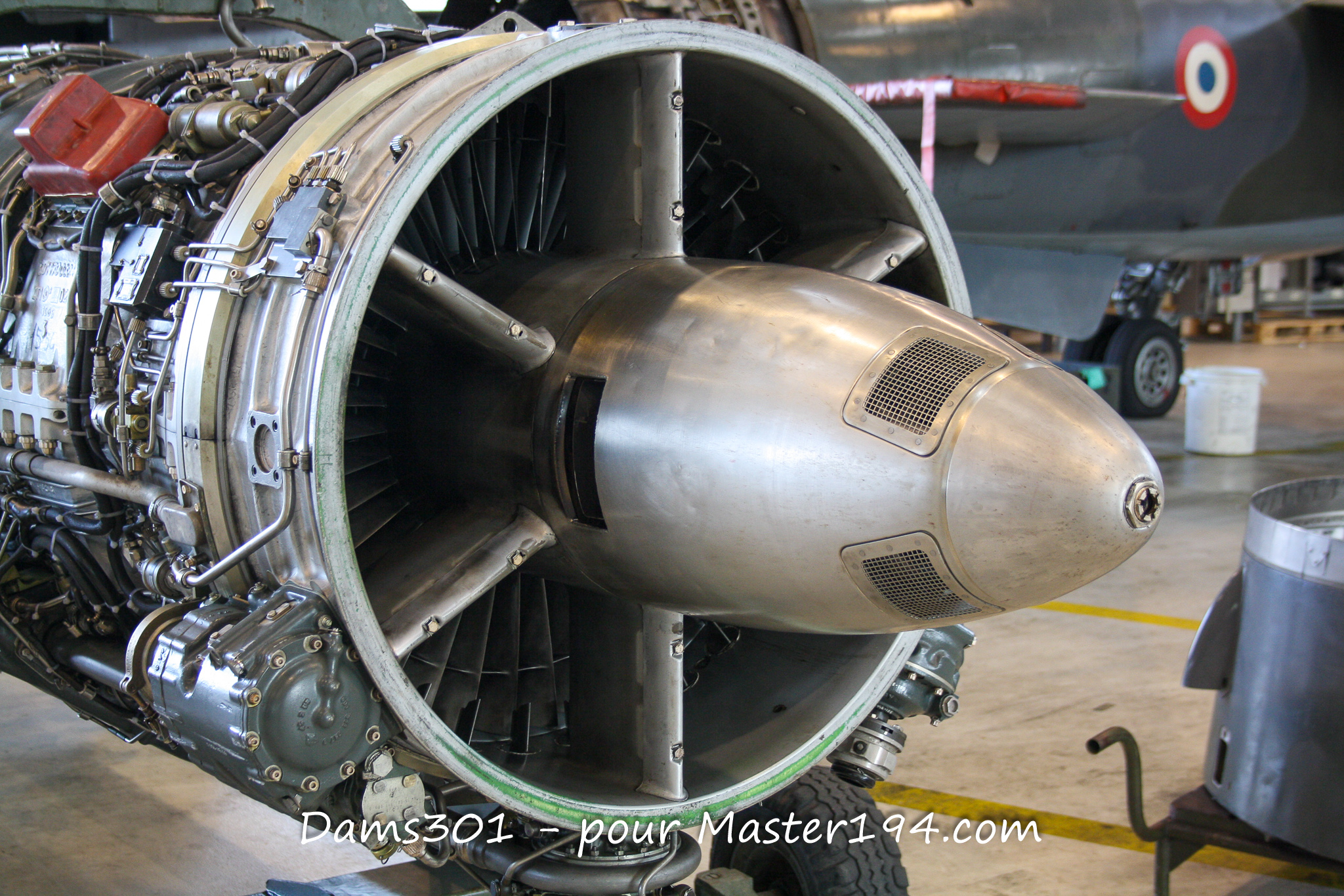
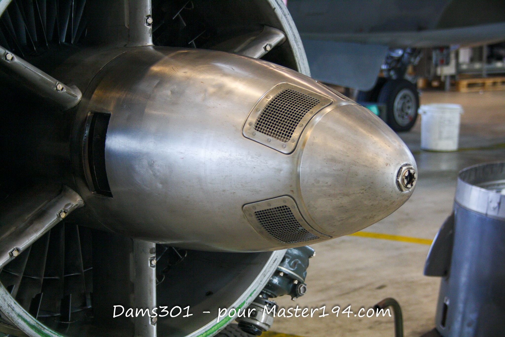
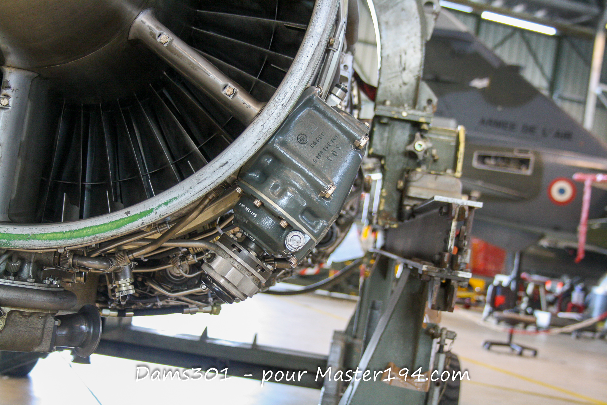
Its architecture remains classic for a military turbojet of this generation. Air enters through the intake, passing through a nine-stage axial compressor. It is compressed before entering the annular combustion chamber, where fuel is injected and ignited.
The hot gases then drive a two-stage axial turbine (supported by a shaft running on two main bearings), which provides the energy required to rotate the compressor. Past the turbine, the exhaust gases enter the afterburner duct and exit through the variable-geometry nozzle.
Directly inherited from the ATAR lineage, this design prioritizes ruggedness, ease of maintenance, and operational reliability across wide flight envelopes rather than seeking high bypass ratios or peak thermodynamic efficiency.
The ATAR 9K50 features a pressure ratio of 6.15:1, a maximum airflow rate of approximately 73 kg/s, and a turbine entry temperature of 935°C. Its dry weight is 1,582 kg, with an overall length of 6.589 m and a maximum diameter of 1.02 m.
A Deeply Modernized Compressor
One of the main upgrades compared to the ATAR 9C involves the compressor section.
While the inlet outer diameter remains virtually unchanged (786 mm), the first two subsonic stages were replaced with transonic stages. This modification significantly boosted air throughput without increasing the engine’s frontal area.
Airflow increased by roughly 6.5% over the ATAR 9C, while thrust output rose by about 10%. The inlet guide vanes (IGVs) were also eliminated, reducing total weight and pressure losses.
This improvement was critical for the Mirage F1: the engine had to deliver more thrust while staying within the tight dimensional constraints of the aircraft’s slim fuselage.
5 Tons of Dry Thrust
The ATAR 9K50 produces approximately 5,000 kgp dry and up to 7,200 kgp with afterburner under standard atmospheric conditions.
| Feature / Spec | SNECMA ATAR 9K50 Specification |
| Engine Type | Single-spool, single-flow axial turbojet |
| Afterburner | Yes |
| Compressor | 9-stage axial (first 2 stages transonic) |
| Turbine | 2-stage axial |
| Max Airflow | ~ 73 kg/s |
| Pressure Ratio | 6.15:1 |
| Dry Thrust | ~ 5,000 kgp (49.0 kN / 4,920 daN) |
| Thrust with Afterburner | ~ 7,200 kgp (70.6 kN / 7,060 daN) |
| Turbine Entry Temp. | 935 °C |
| Rotational Speed | 8,400 RPM (up to 8,900 RPM at Mach > 1.4) |
| Dimensions | Length: 6,589 mm / Max Diameter: 1,020 mm |
| Dry Weight | 1,582 kg |
(Note: Depending on reference sources and test conditions, thrust ratings may vary slightly. CAEA lists 4,920 daN dry and 7,060 daN with afterburner).
Variable Nozzle Afterburner
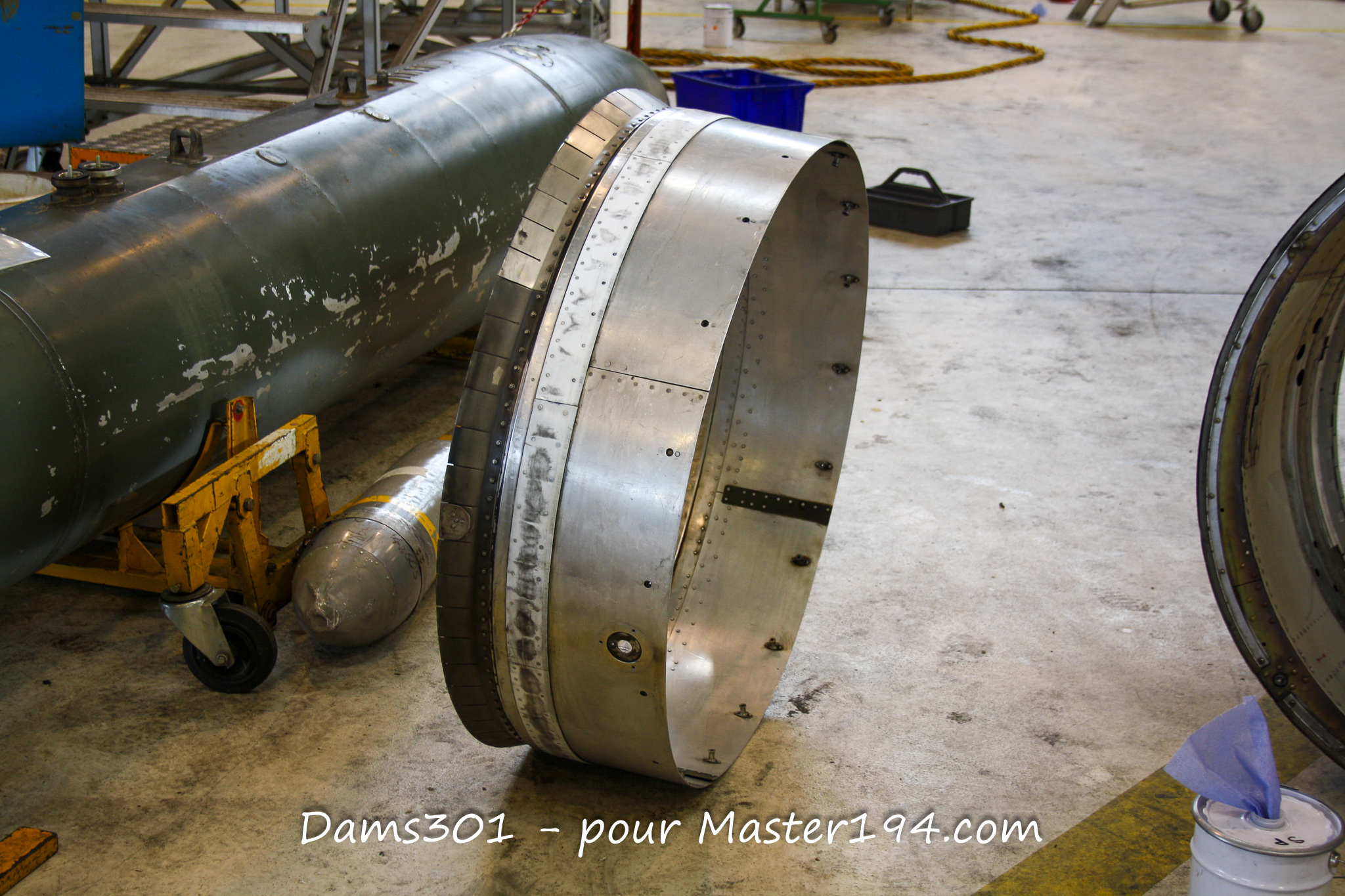
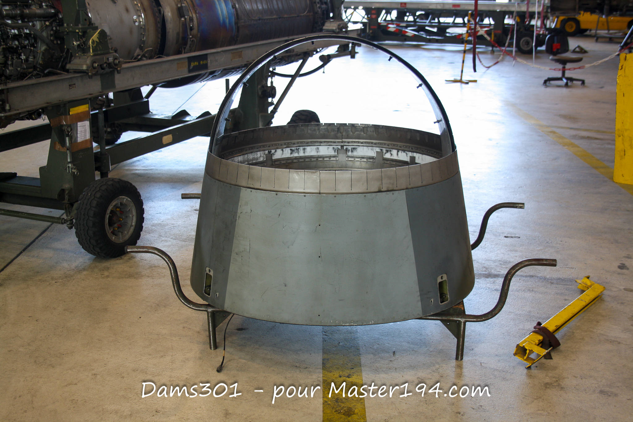
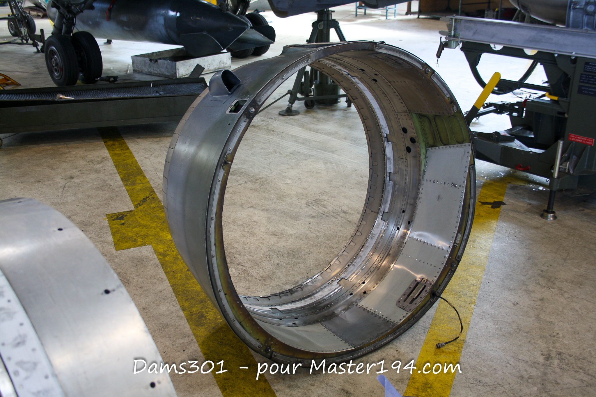
As with previous ATAR 9 variants, the afterburner duct is installed downstream of the turbine.
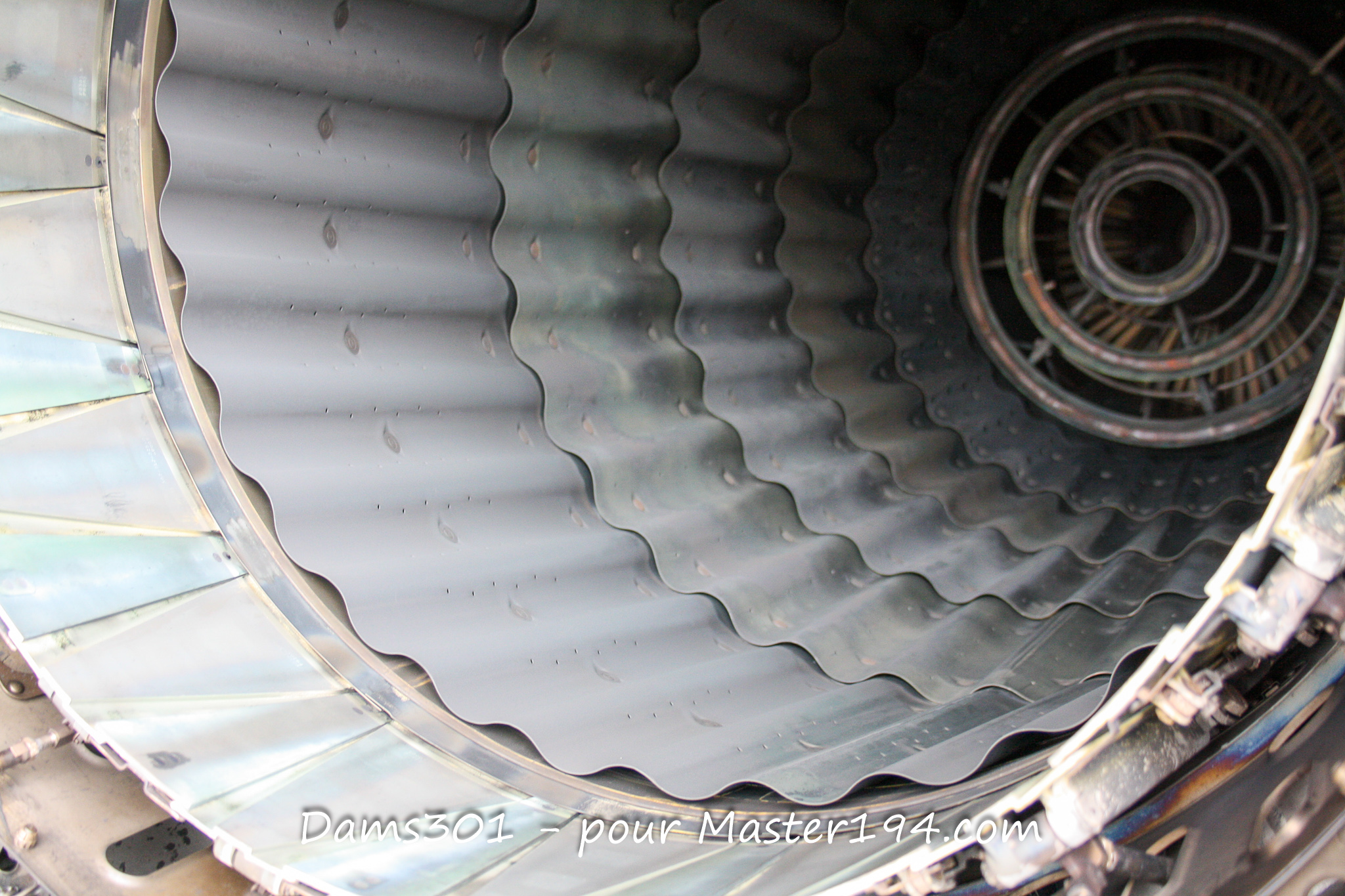
It operates by injecting additional fuel directly into the hot exhaust gas stream exiting the turbine. Burning this fuel drastically raises gas temperature and exhaust velocity, providing the extra thrust needed for rapid acceleration and supersonic breakout.
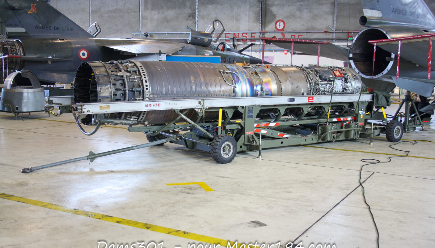
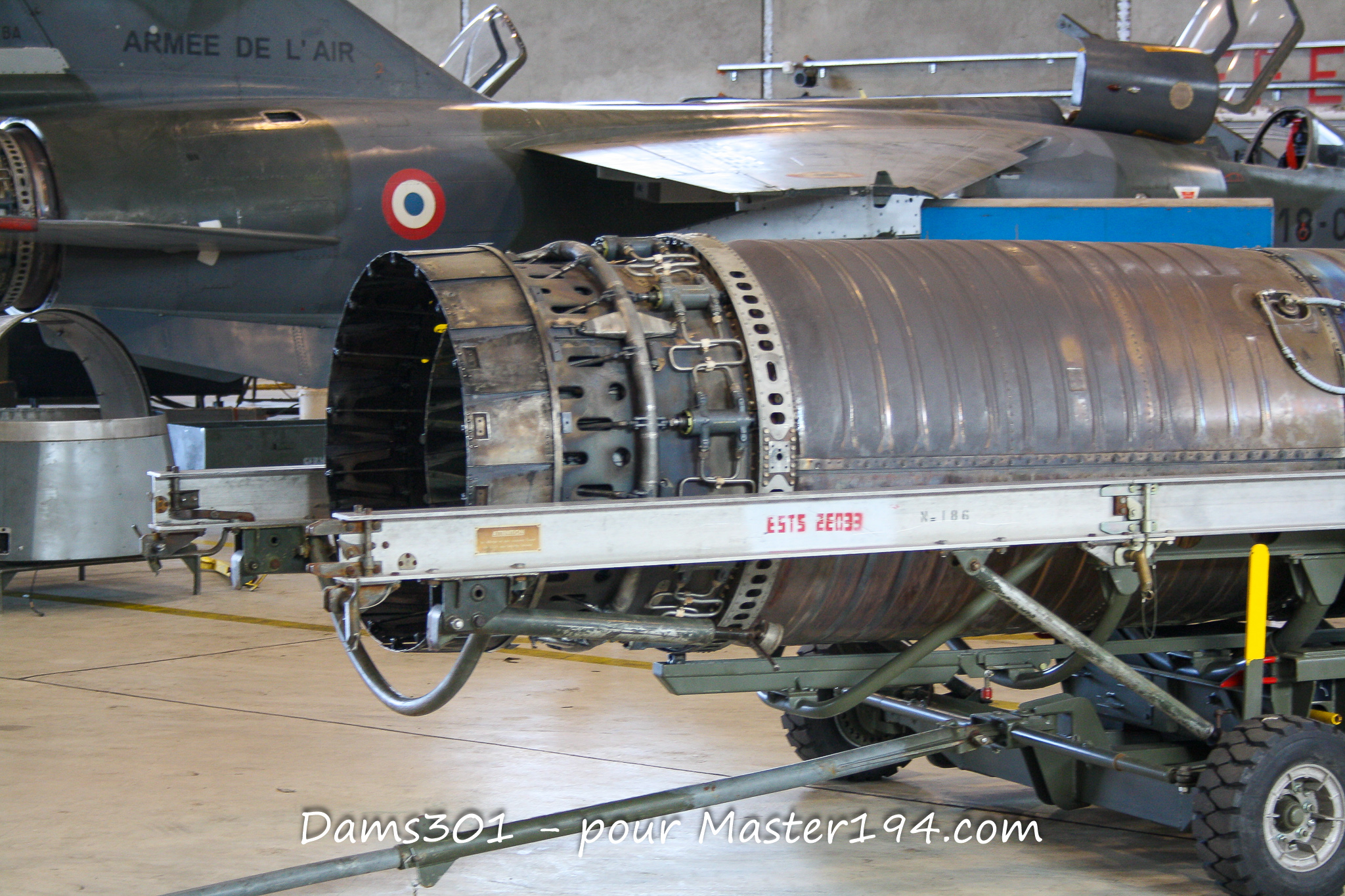
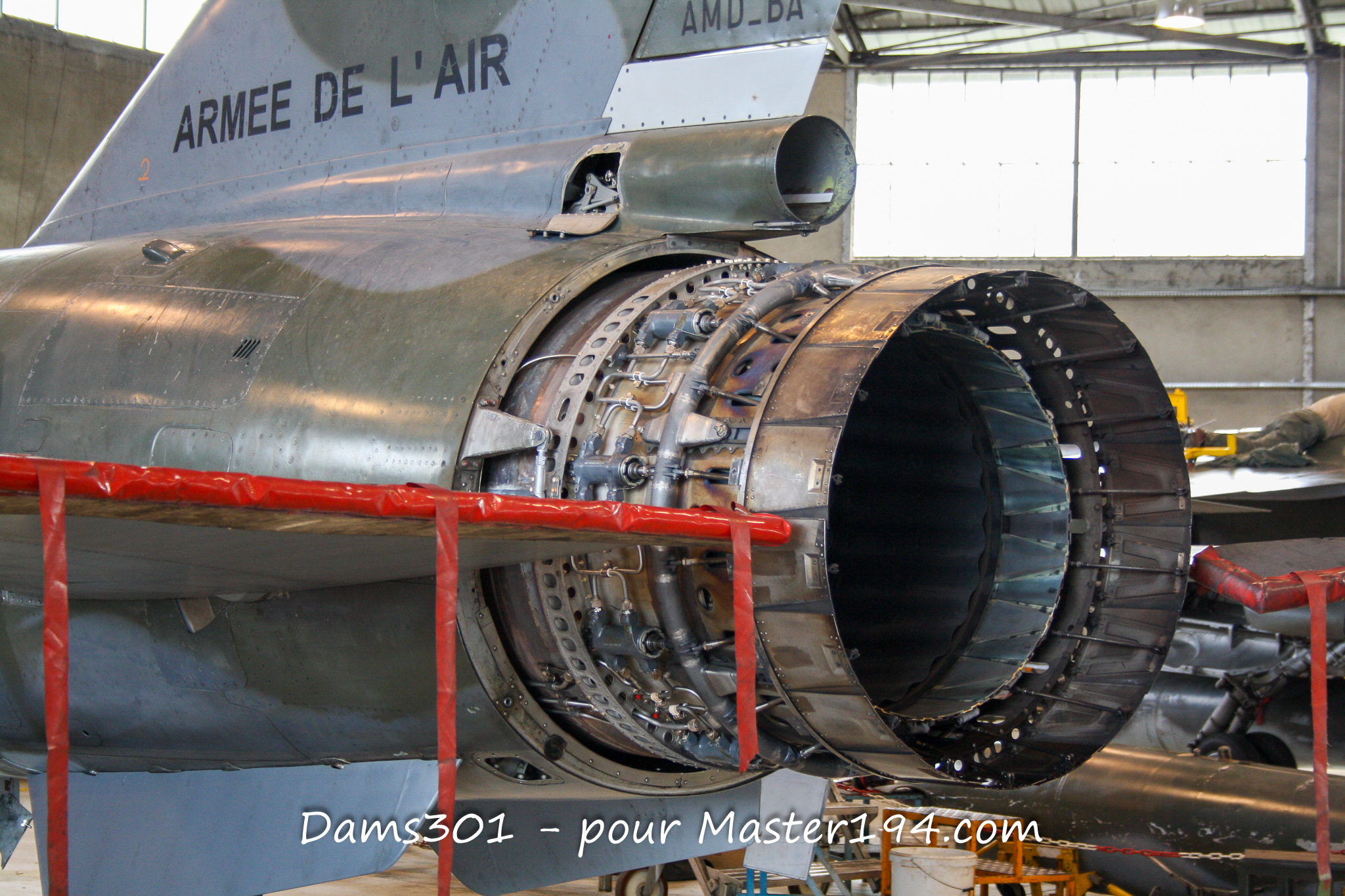
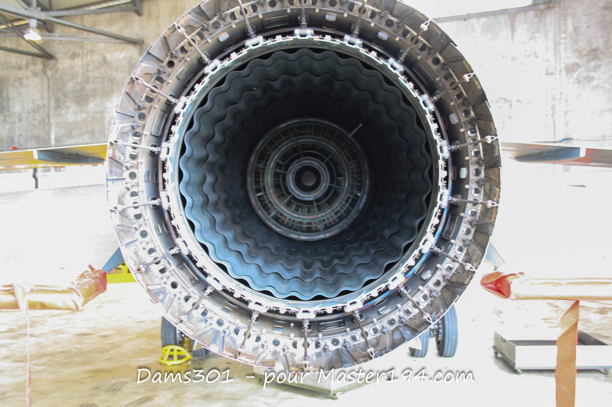
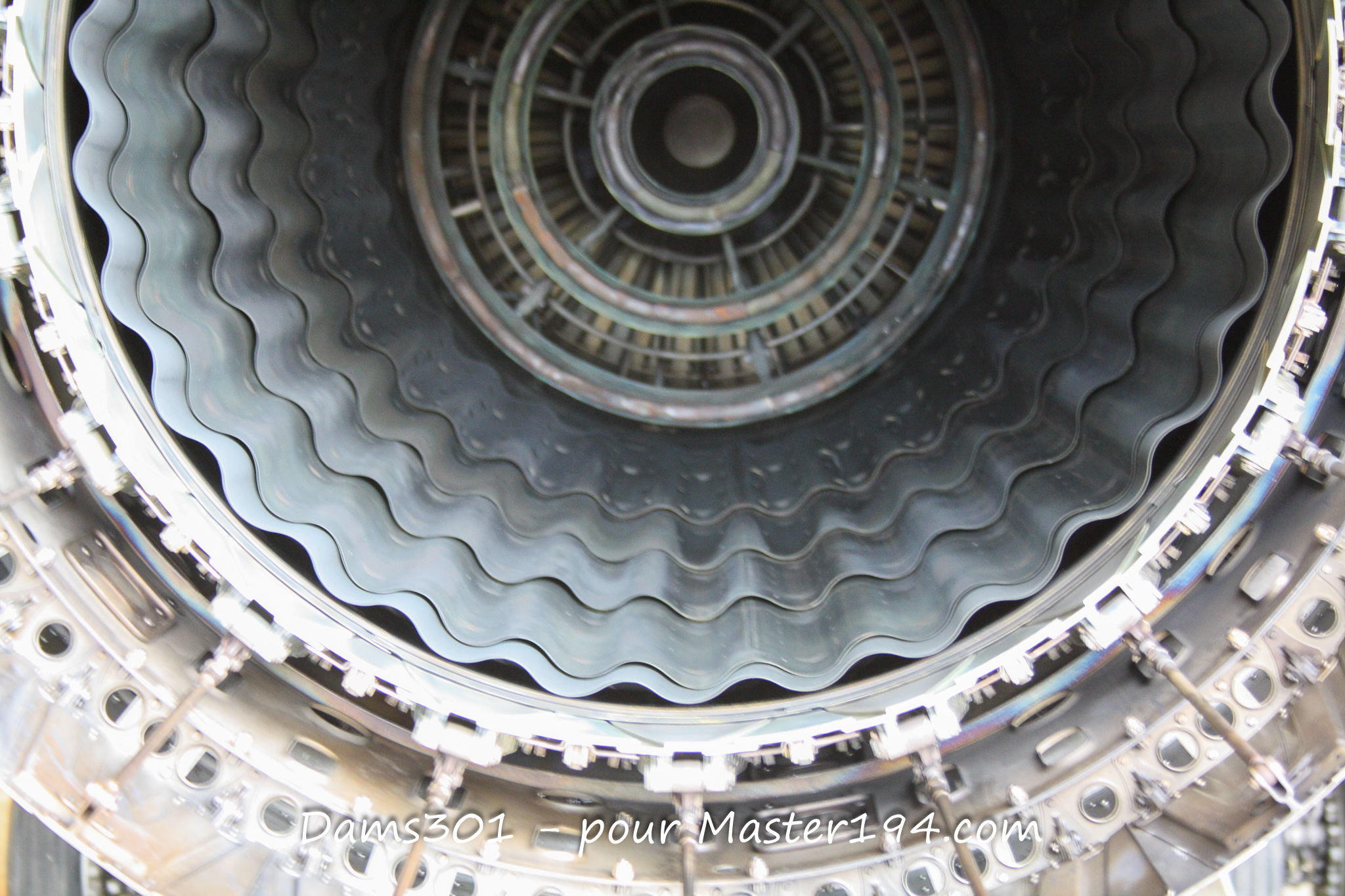
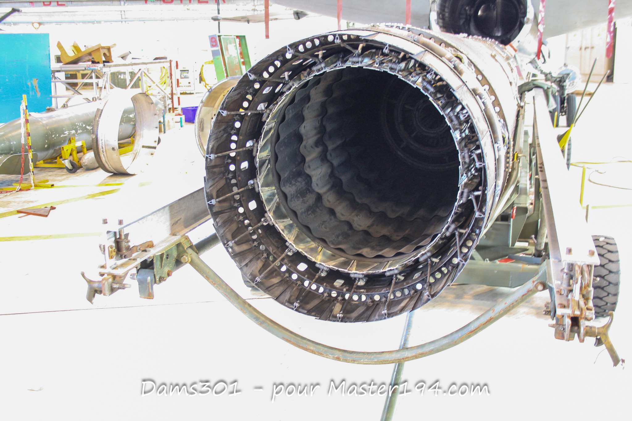
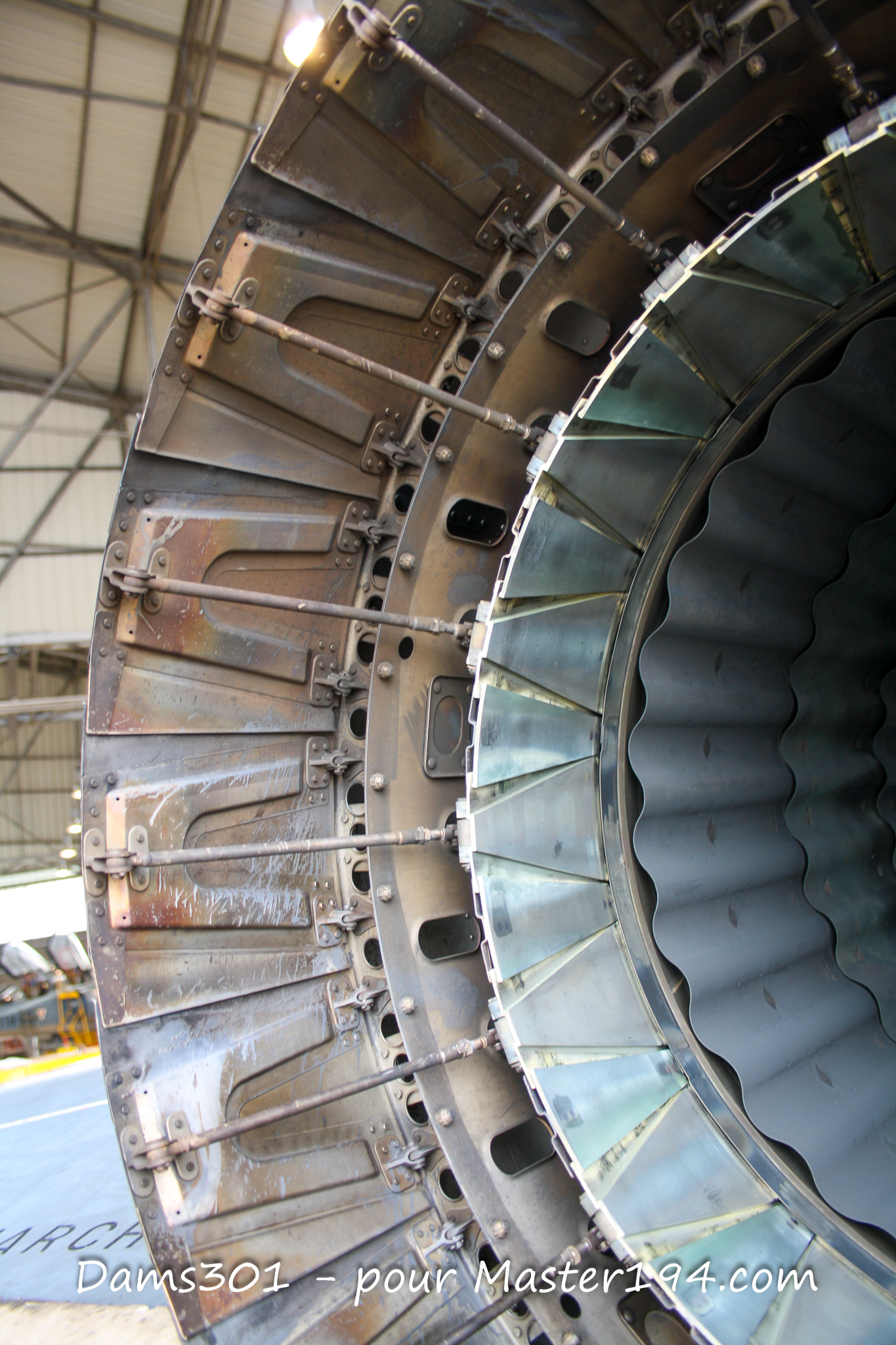
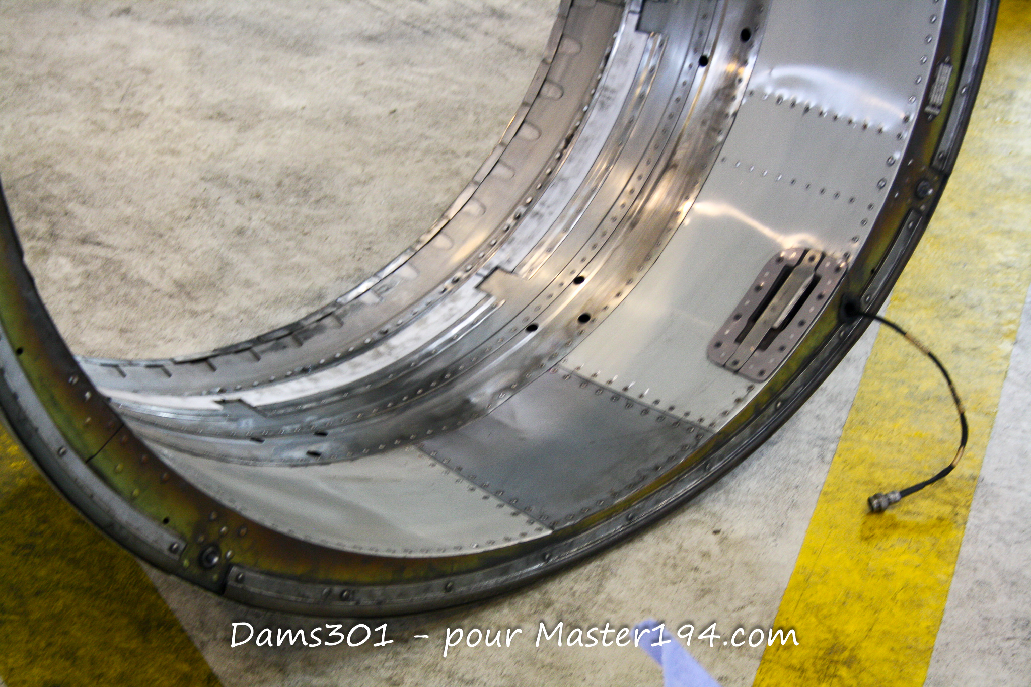
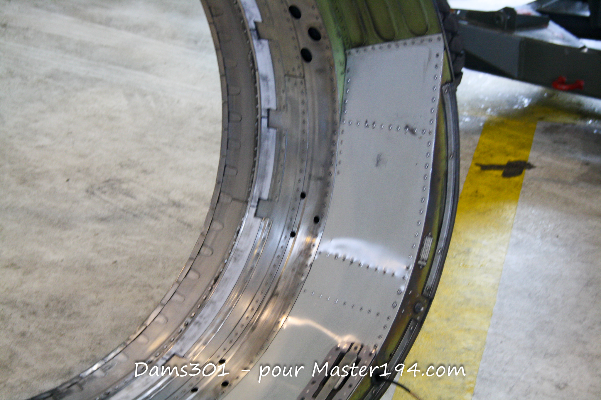
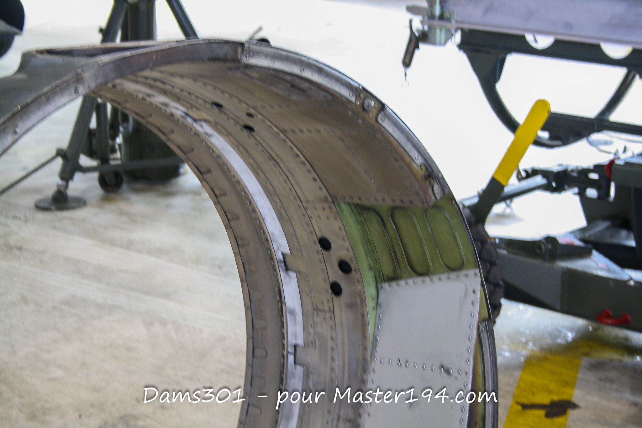
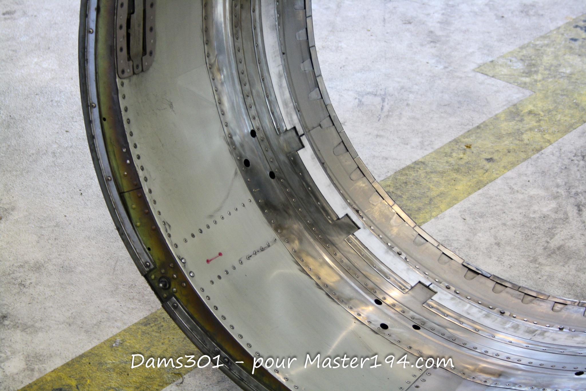
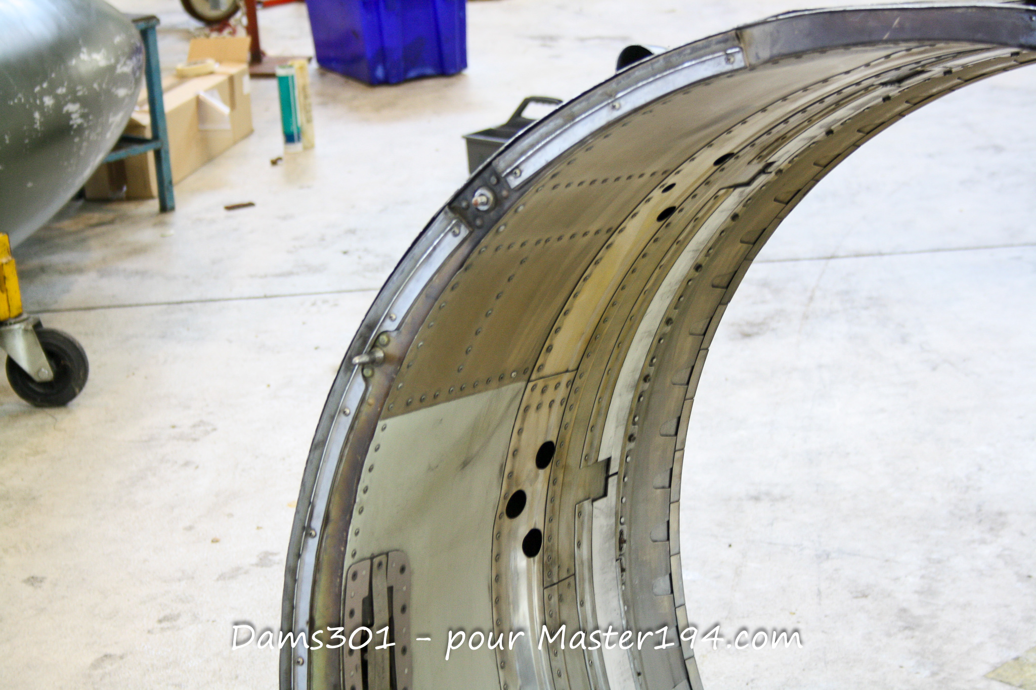
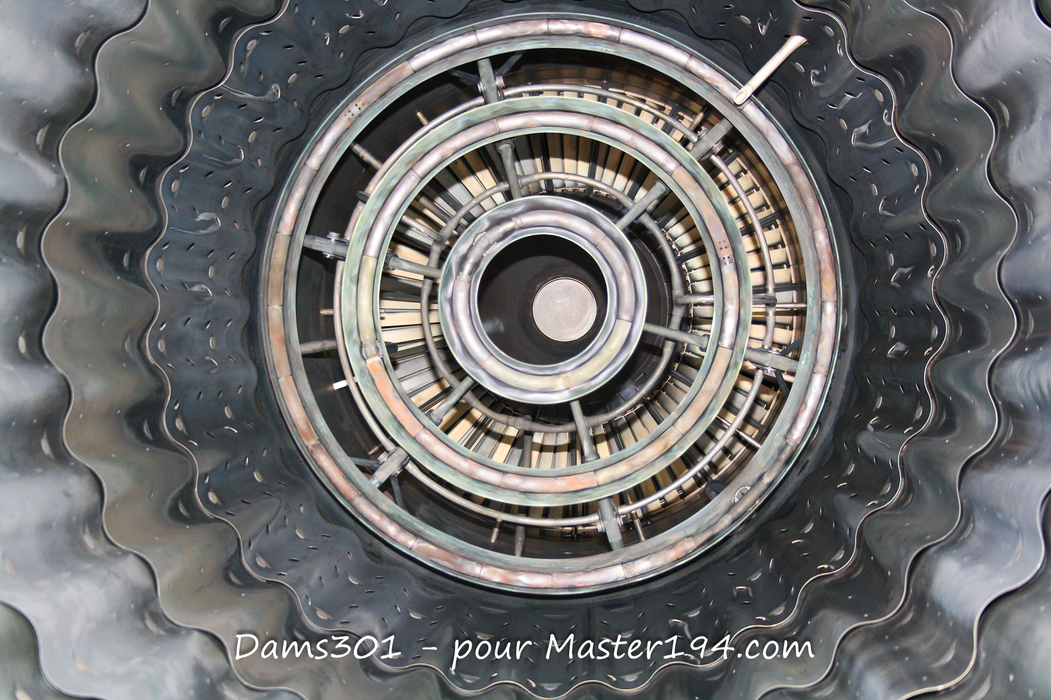
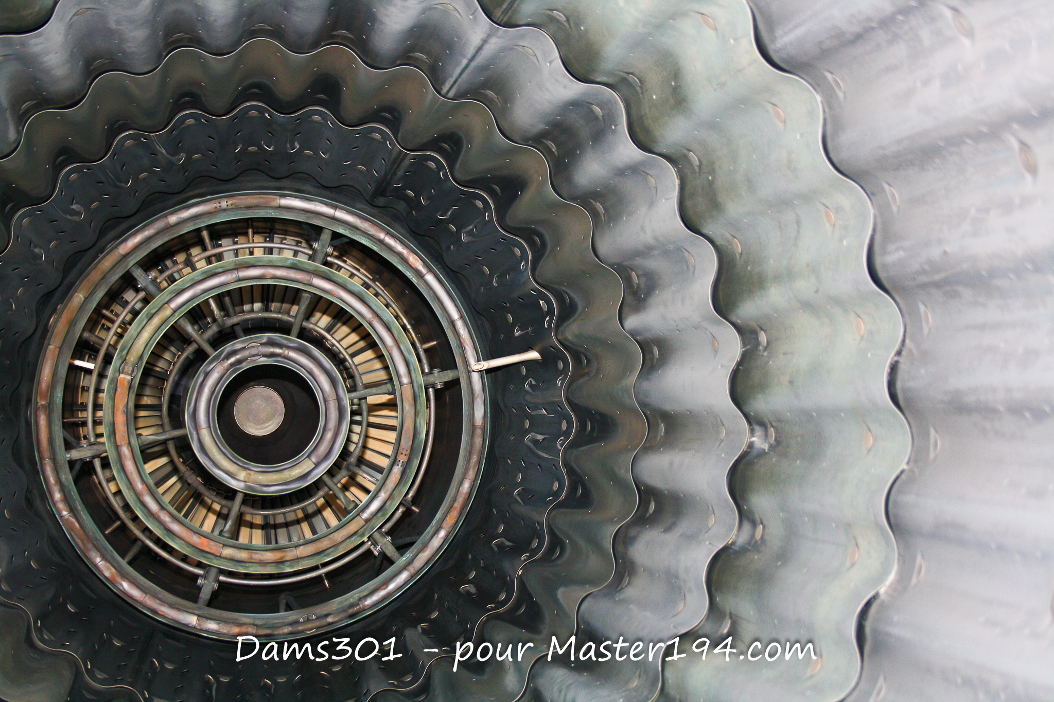
To adjust the throat and exit areas to these major fluctuations in flow volume and temperature, the ATAR 9K50 features a convergent multi-petal variable nozzle.
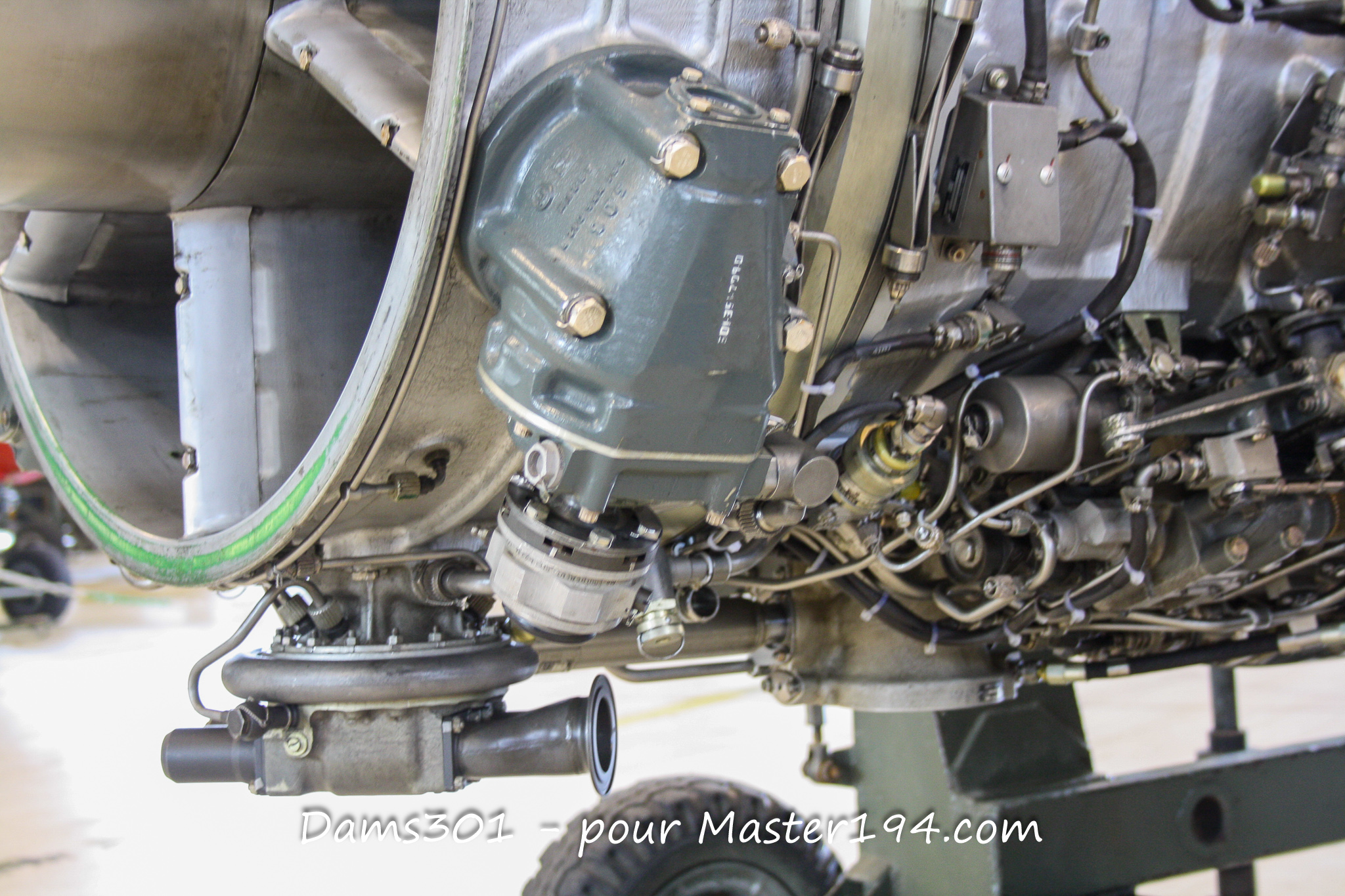
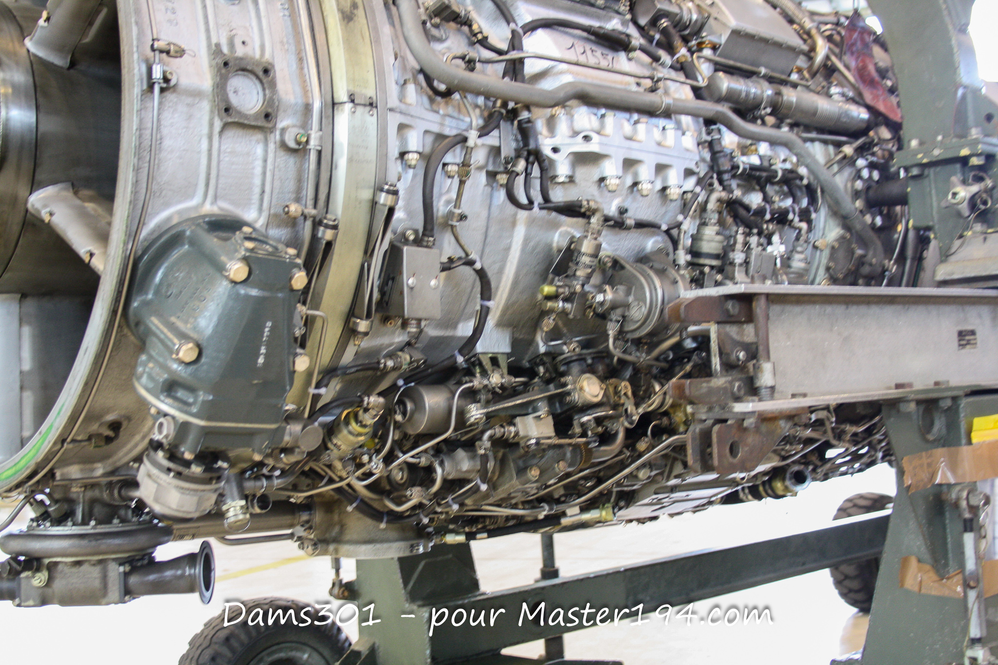
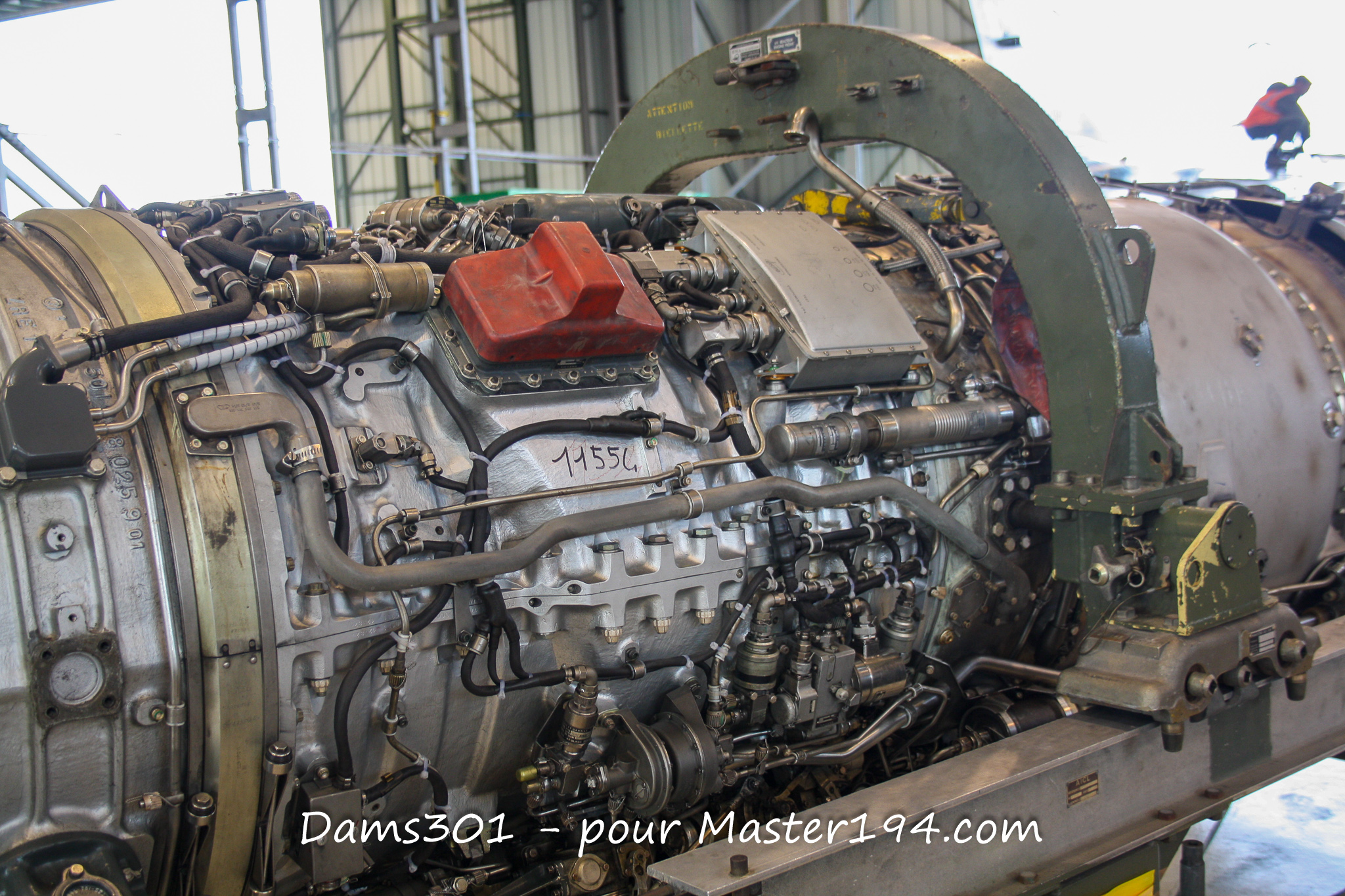
On a dismounted engine or museum exhibit, this nozzle assembly is one of the most visually distinctive components. Its petals, control linkages, and hydraulic actuators are instantly recognizable to aviation enthusiasts and scale modelers.
Enhanced Engine Control System
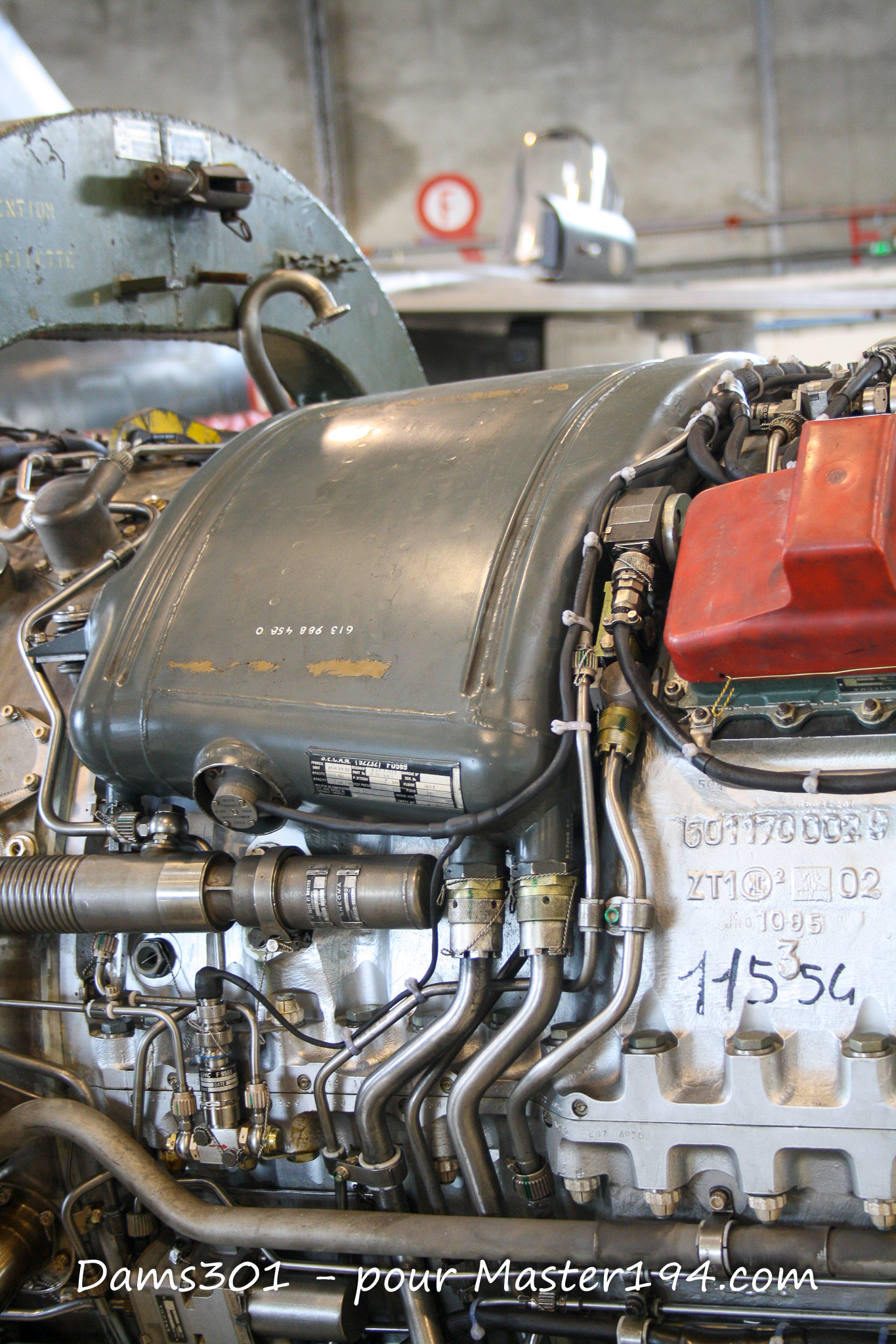
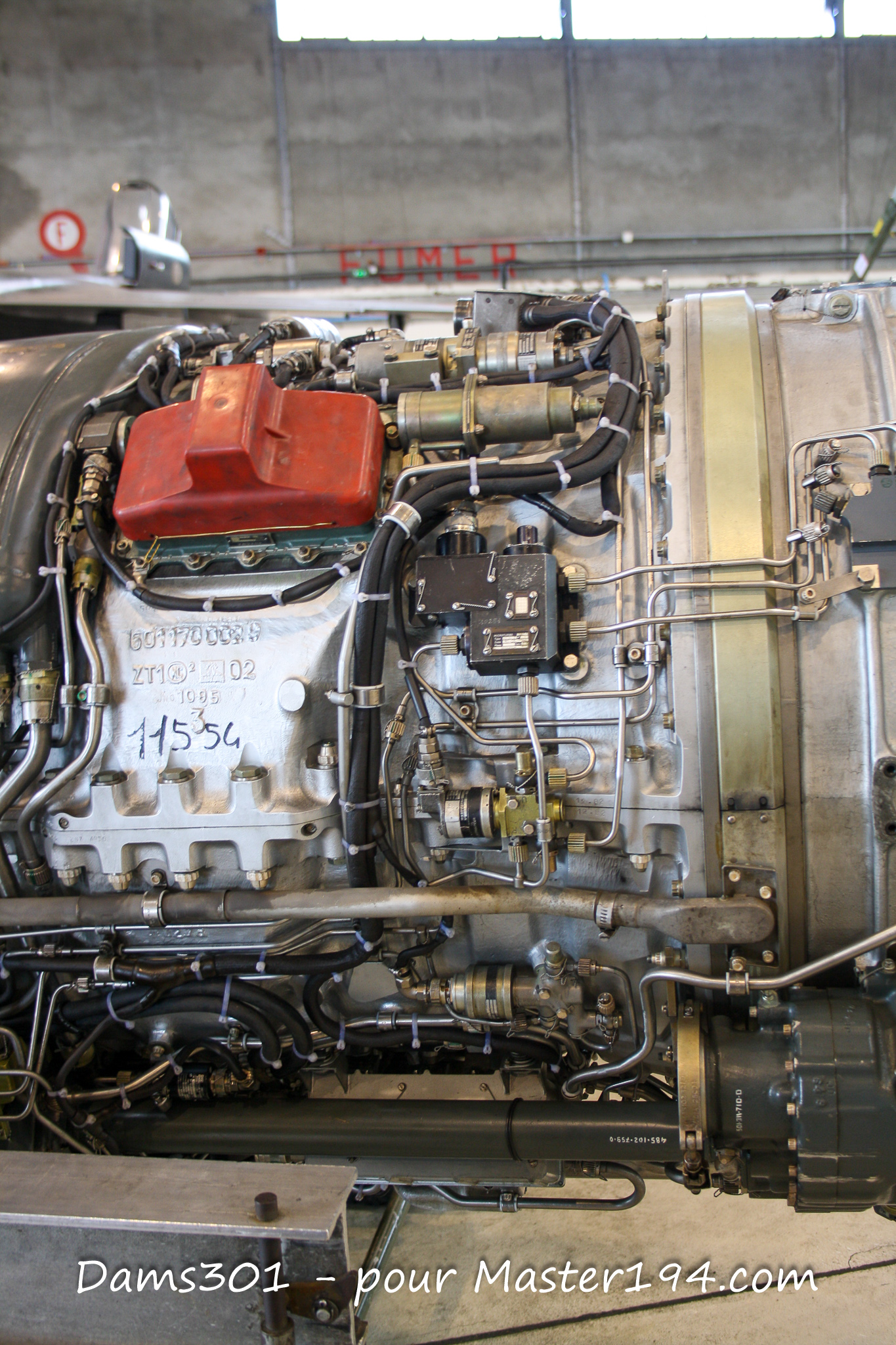
The 9K50 offers more than just extra power over the original 9K. Engine governing is fully automatic for rotational speed and temperature, combining proven hydromechanical controls with electronic assistance.
Several dedicated features protect operation at the edges of the flight envelope:
- Anti-stall Protection: Bleed valves located on the first compressor stages prevent compressor surge during rapid throttle movements.
- Supersonic Overspeed: The engine can increase its rotation speed up to 8,900 RPM when airspeed exceeds Mach 1.4.
- High-Altitude Optimization: A dedicated system adjusts afterburner fuel injection to maintain flame stability at high altitudes.
Engine Engineered for the Mirage F1 Airframe
The selection of the ATAR 9K50 was central to the Mirage F1 requirement profile. The new fighter was meant to succeed the Mirage III by improving range, payload capacity, and low-altitude maneuverability, while preserving Mach 2.2 interception capability and a service ceiling of 18,500 meters.
This operational versatility required a powerplant capable of enduring rapid throttle adjustments, violent accelerations, and prolonged afterburner usage without flameout risks.
You can read our complete Mirage F1 reference file here:
Dassault Mirage F1: Ultimate guide, walkarounds & scale modeling
Production and Legacy: Transition to the M53
In total, 1,014 ATAR 9K50 engines were produced by SNECMA. Beyond powering the Mirage F1 (across its C, CT, CR, and export variants), it was also installed on the Mirage 50 and selected testbeds based on the Mirage III.
It marks the culmination of nearly thirty years of development within the ATAR family. Although basic and fuel-thirsty compared to modern turbofans, its mechanical reliability and ease of maintenance proved themselves across all operational theaters.
Its natural successor was the SNECMA M53, developed for the Mirage 2000. Marking a major technological shift, the M53 adopted a unique single-spool, low-bypass turbofan formula, bridging French military engine design into the next generation.
Explore our dedicated Mirage 2000 dossier here:
Dassault Mirage 2000: Technical Walkarounds, Airframe Details & Scale Models