 by
Wheel wells and engines
I then focused on the wheel wells, and more specifically on the landing gear strut and the layout of its housing. It is practically a model within a model!
Part of these components had to be made of metal, notably using Albion Alloys profiles, to ensure the structural strength required for the aircraft’s final weight.
I first had to understand how the real system worked. For a moment I considered simplifying this fairly complex assembly, before coming back to my senses. My model is meant to be a sort of three-dimensional monograph: I therefore had to try and replicate reality as closely as possible.
AD
The engineers who designed the real aircraft also had to solve the challenges of strength and kinematics. They used a triangulation setup to transfer loads, a drag strut to lock the assembly in place, and an actuator that, upon retracting, “breaks” the landing gear in half and swings the wheel backward into the bay. It therefore becomes quite natural to follow their design. You combine an understanding of the mechanism with both strength and simplicity.
The wing box houses the landing gear pivot and the actuator anchor point.
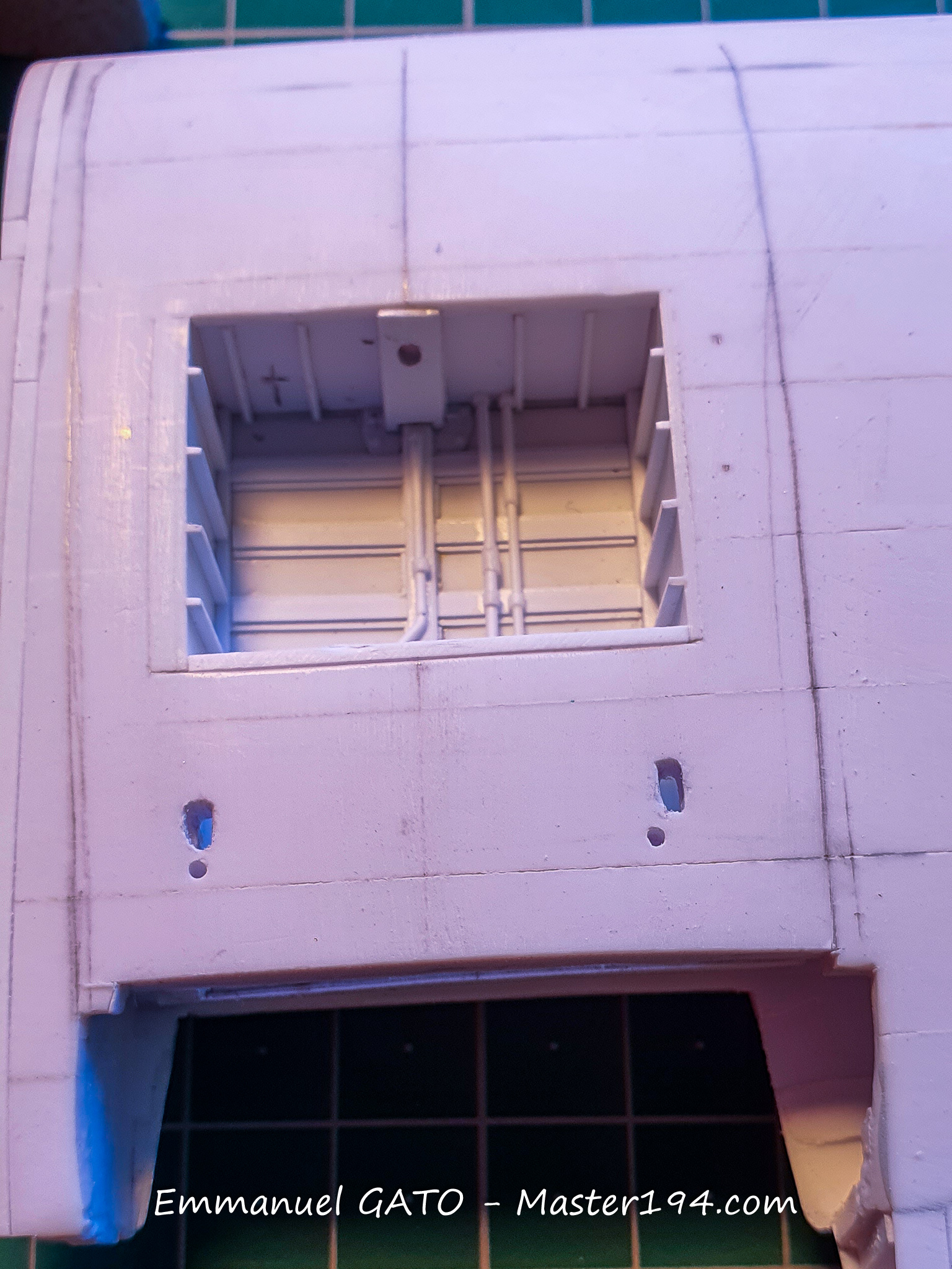
All the parts that will make up the wheel well. The interior skin complete with stringers, which will conceal the openings in the tail boom structure, is still missing.
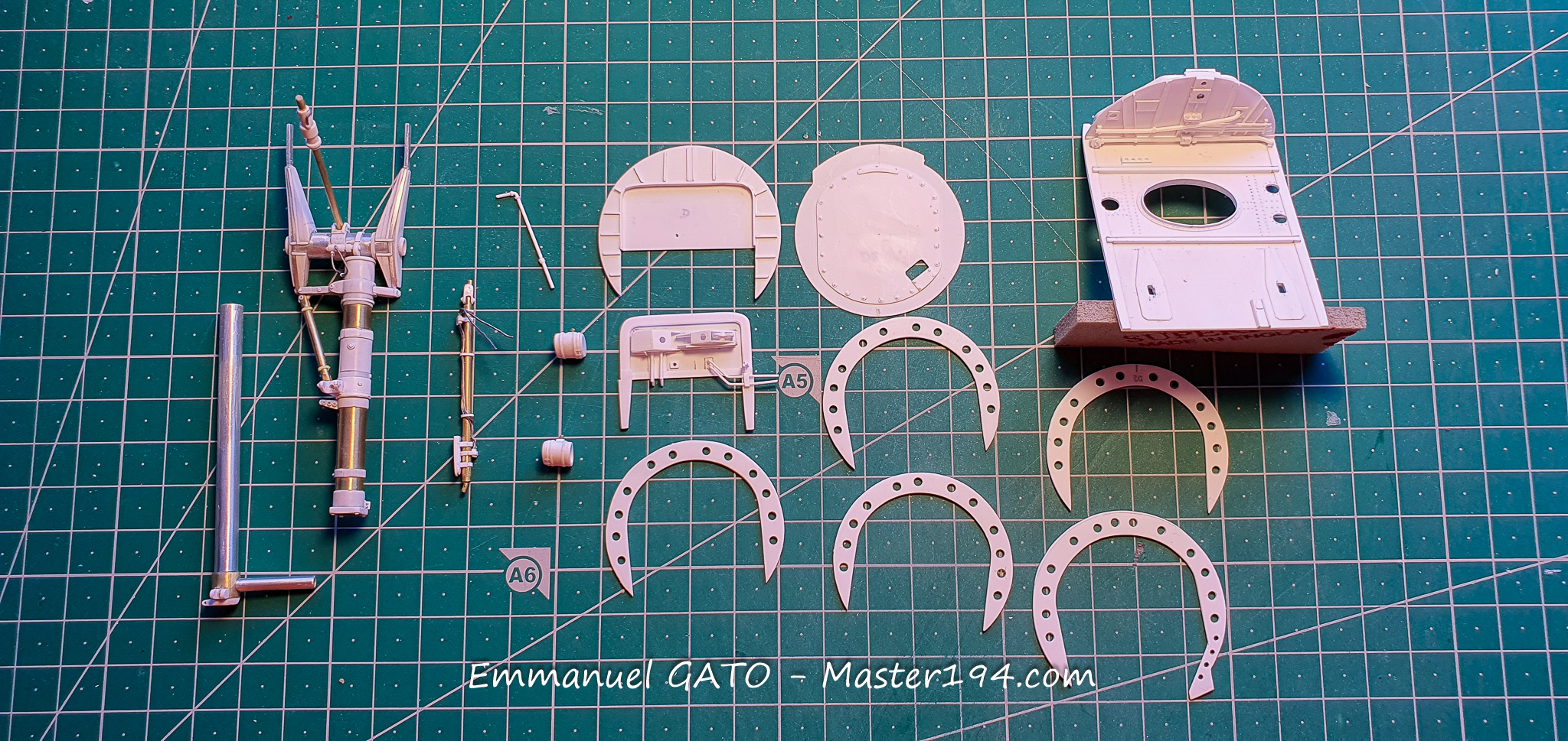
The right landing gear seen from the front.
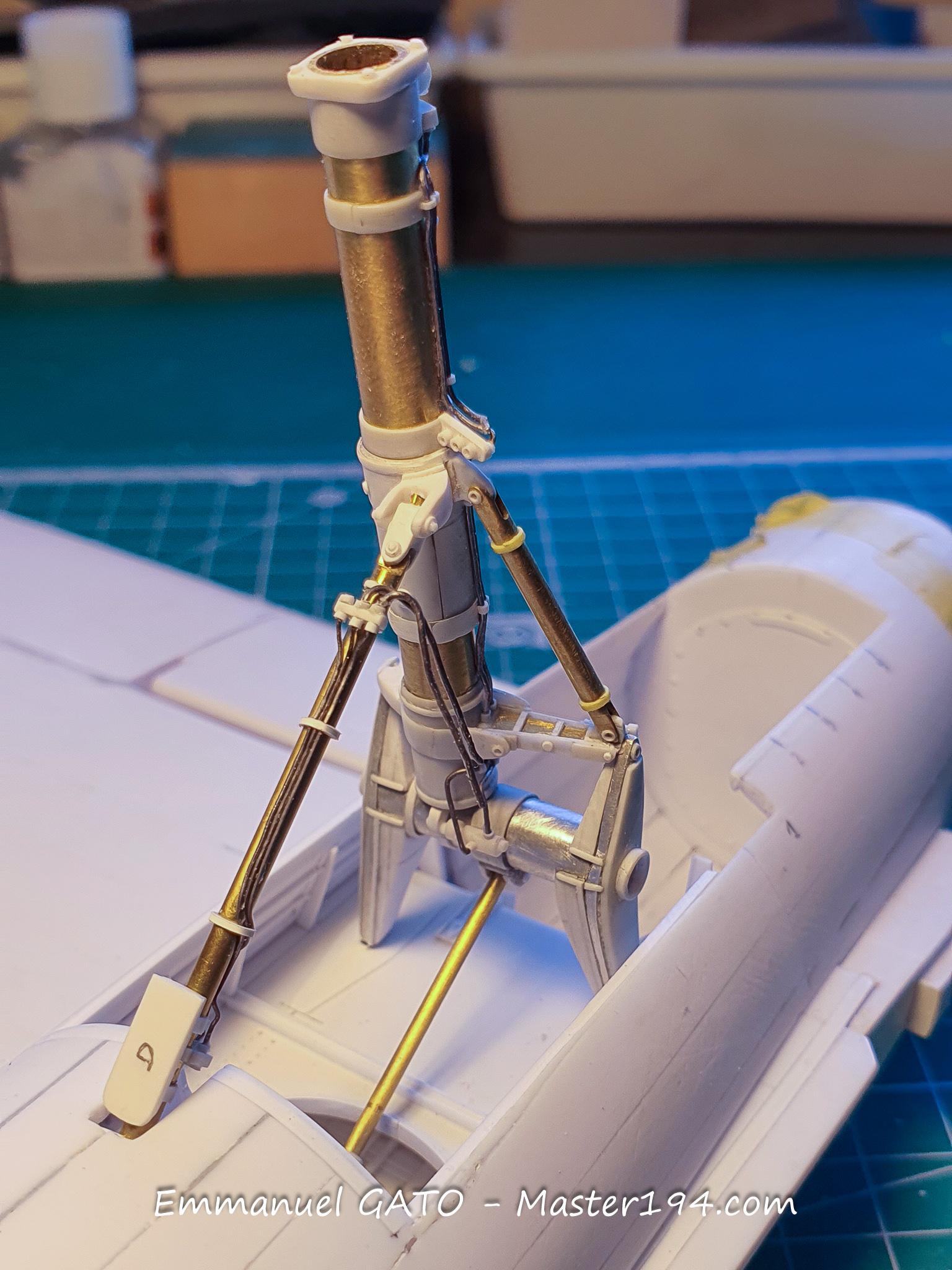
And the same seen from the rear.
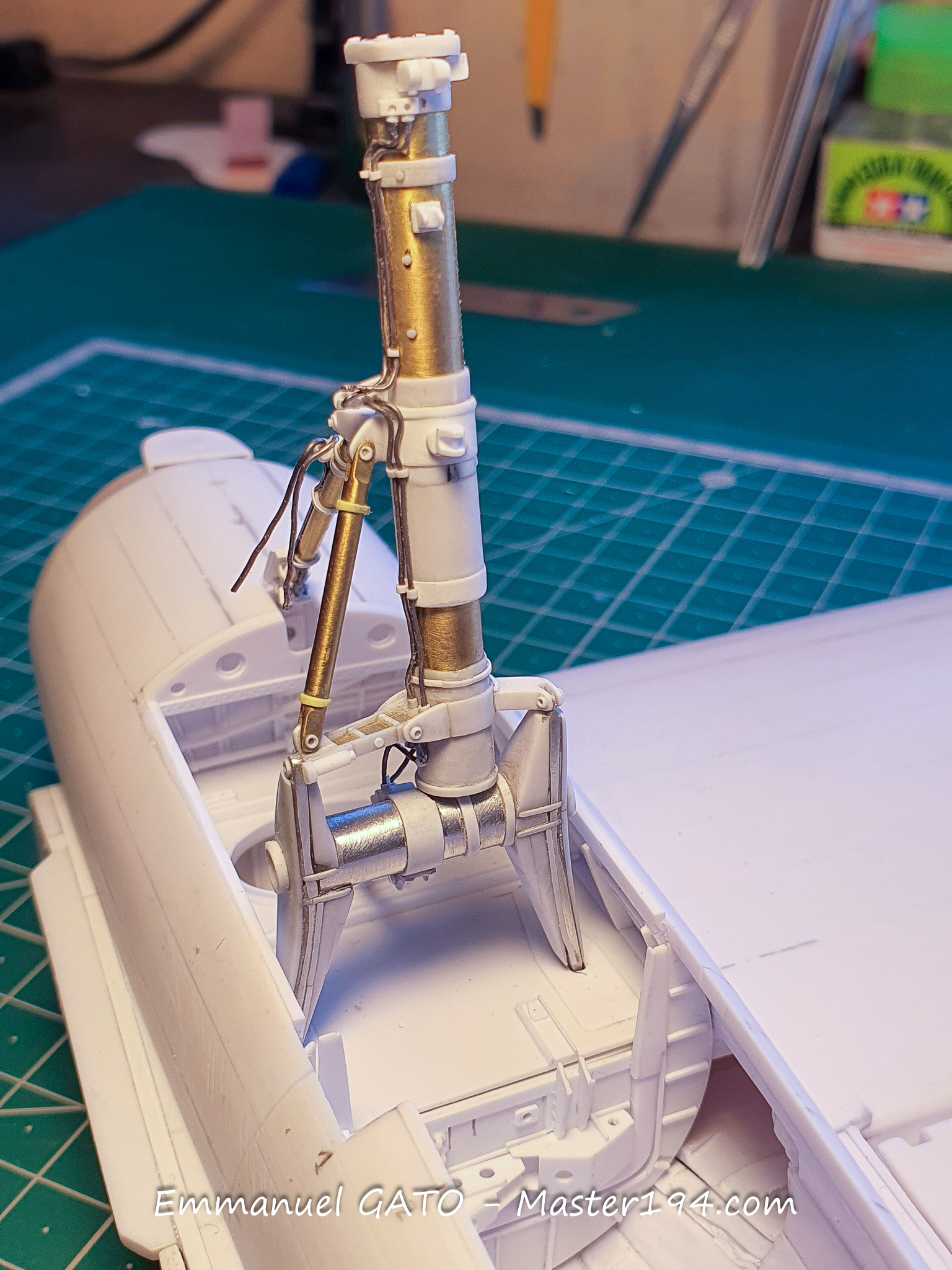
There are still plenty of details to add: the doors, cables, hydraulic lines, and the interior lining of the bay. The whole assembly will then need to be painted before being masked off for the rest of the build. I also plan to turn the nose and main wheels on a lathe, which will mark another major milestone.
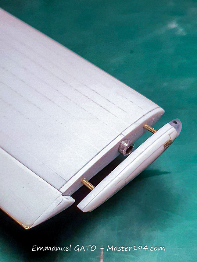
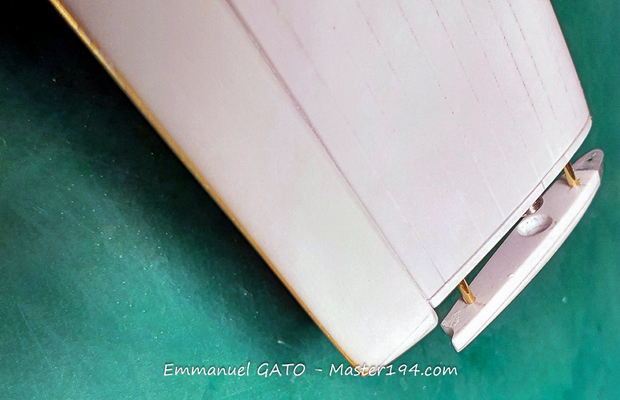
The mounting system for the outer wings is taking shape. A 3 mm threaded rod runs through the wing and anchors into a female receiver located at the wing root. Tightening is done from the wingtip using a steel Parker screw. You just need to apply a slight amount of tension to draw the two sections tightly together.
Of course, this screw will need to be concealed at the tip of the wing. Quite a bit of engineering work just to avoid ending up with a one-meter wingspan that’s impossible to transport!
The wingtip is now finished, along with the alignment and mounting system. The ailerons are also in place. Their trailing edge is made from an Albion Alloys flat copper strip, which accounts for its golden-yellow color. This solution offers several advantages: a consistent 0.4 mm thickness over a long span, an excellent guide for the styrene sheet, and better resistance to the minor knocks that inevitably happen in this area.
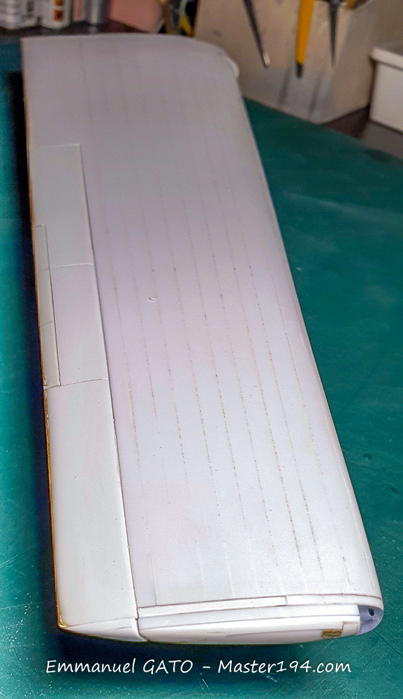
My goal remains to finish the wings and the center wing section before moving on to the tail booms and empennage. The fuselage and its interior detailing are obviously tempting, but the sheer size of the parts demands a methodical approach. Once the wing is mated to the fuselage, all sub-assemblies will need to drop right into place without having to flip the model over in every direction.
I therefore turned my attention to the engines. Let’s be clear: it’s mostly about giving the impression that there are engines inside the cowlings, since very little will actually be visible in the end.
On the real aircraft, the cowlings are remarkably efficient. The cooling air intake gap for the cylinders, between the spinner and the cowling lip, measures only 11 cm—or roughly 0.3 mm in 1/32 scale. This gap is so finely calculated that there are no cowl flaps like you see on many other high-powered engines.
Here are the components made for the model.
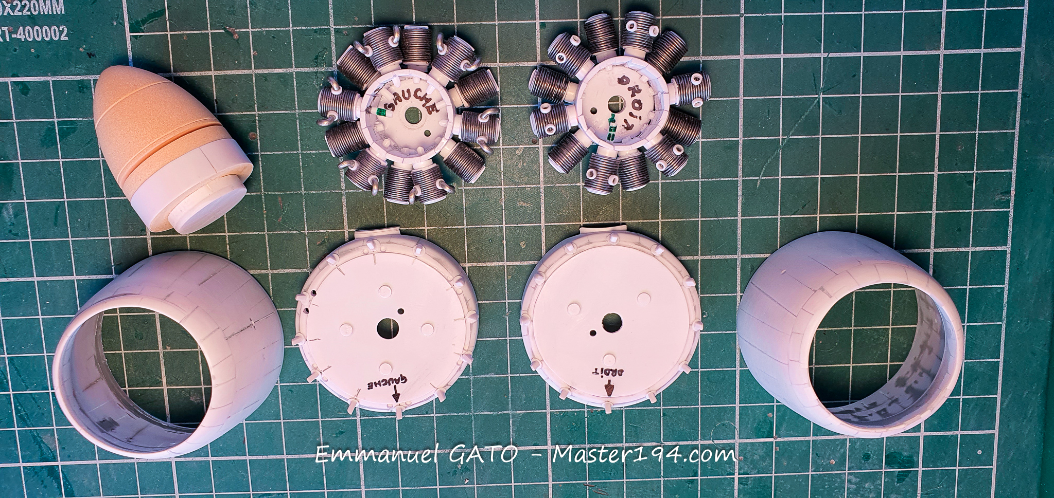
All the parts making up the powerplant assembly: the two 2,040 hp SNECMA “Hercules” engines, the cowlings, the ring cowling support that holds the cowling on the real aircraft, and the propeller spinner.
The cylinder cooling fins are represented using 0.5 mm lead wire—the kind used for fly tying—wrapped around a plastic rod. With a bit of drybrushing, it should do the trick nicely.
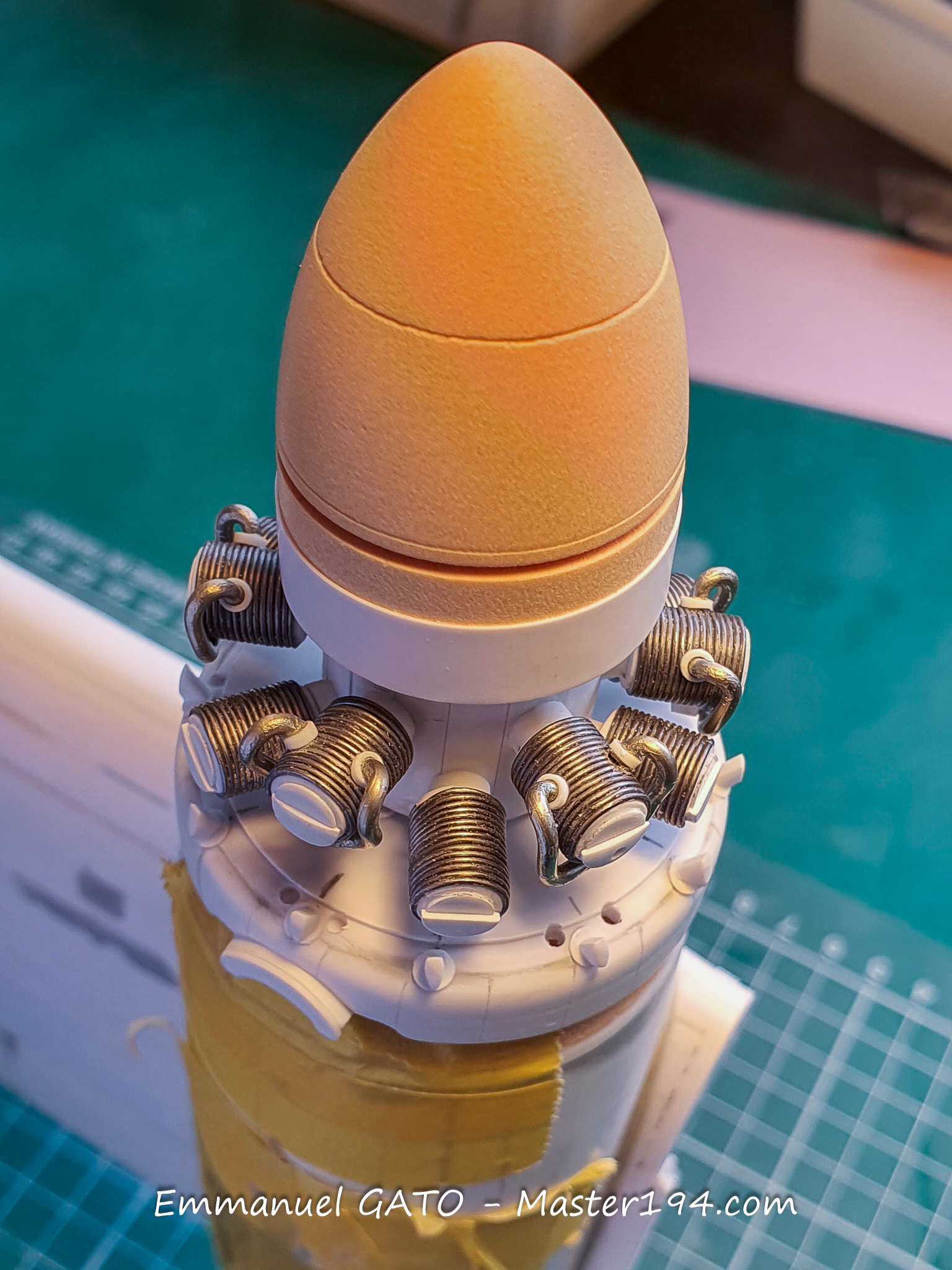
The engine is installed, along with a rough mockup of the exhaust stacks. You can really see the imposing size of the spinner, which helps narrow down the cooling intake gap. The spinner was turned on a lathe from “Lab” [urethane tooling board], a fairly porous material that will need a coat of automotive primer before casting resin copies.
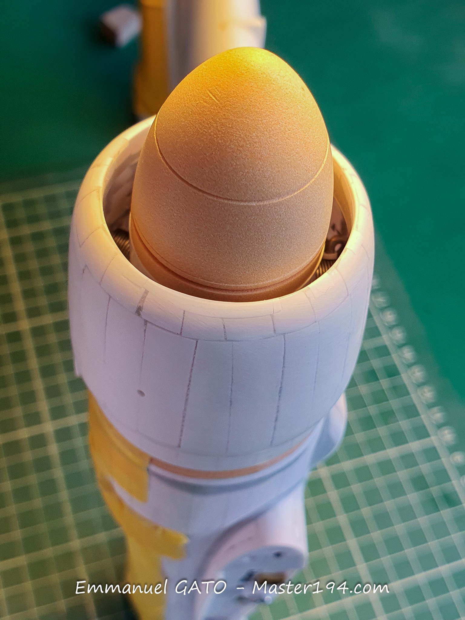
Everything is now assembled—and as expected, you can barely see anything inside anymore! The cowling will be held in place by through-rods made of plastic that anchor into the engine cylinders.
The whole assembly can be installed once the center wing box is mated to the fuselage, which will significantly cut down on handling the model.
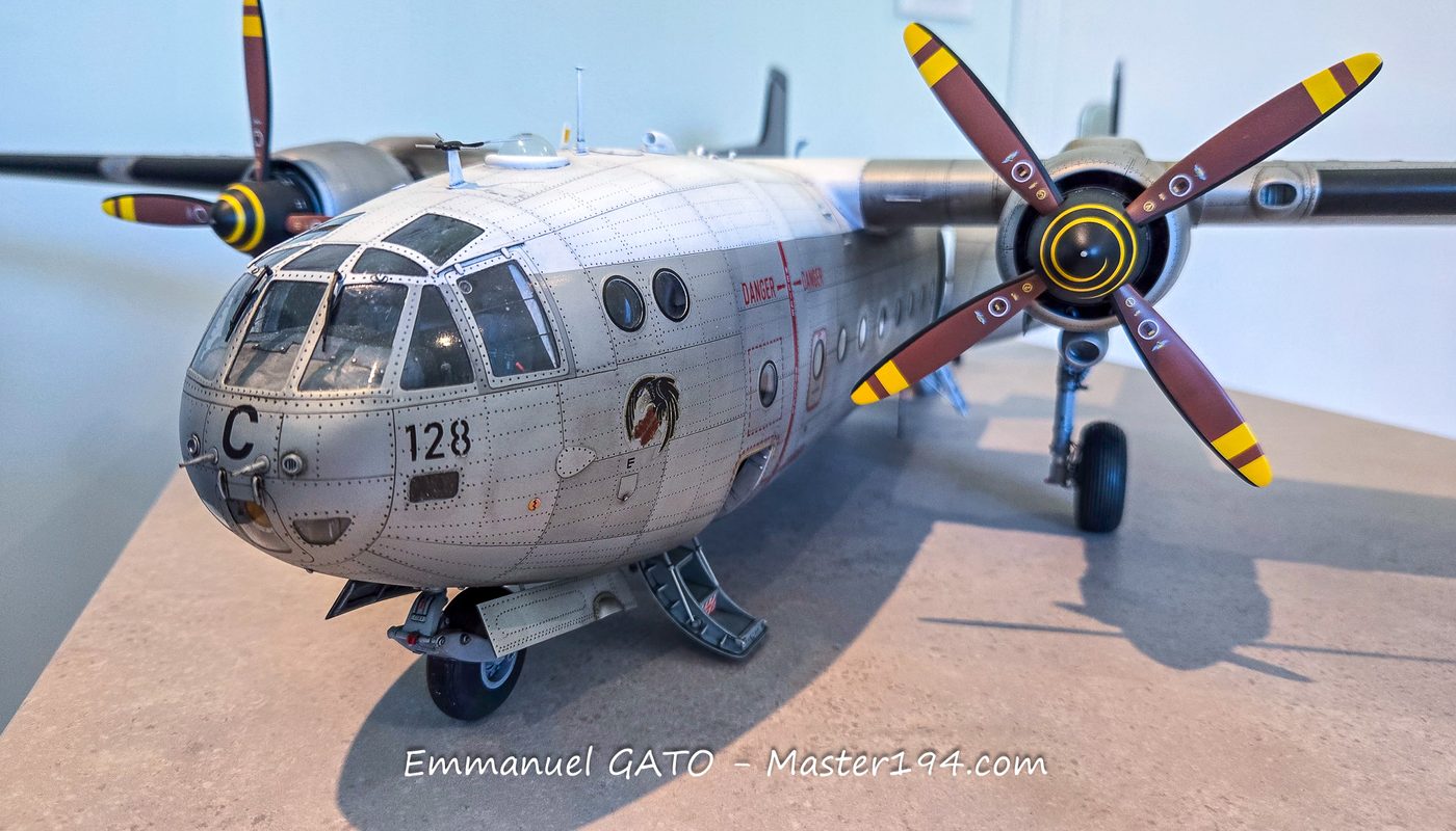
The center wing box is truly the keystone of the aircraft, just like on the real Noratlas. It supports both engines, the main landing gear, the outer wings, and the tail booms. The fuselage will then attach underneath it. It therefore has to bear a good portion of this old Nord’s weight.
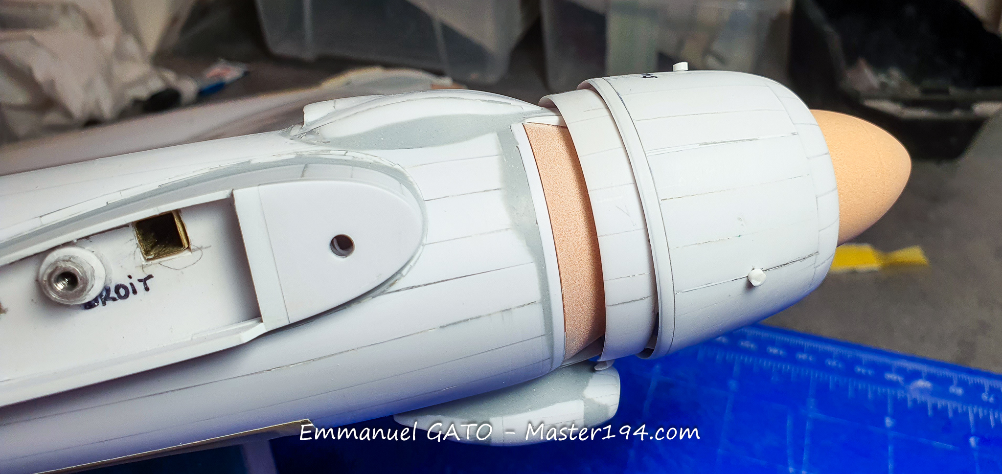
After finishing the engines, I looked for a way to secure their cowlings. The approach I settled on involves drilling through the cowlings to insert Evergreen rods that anchor into the cylinders. These are the little pins visible in the photos; they will be trimmed flush at the end.
Beneath the engines sit the oil coolers, with their rather convoluted shapes and blended fairings. Once again, I used Sintofer Pierre [two-part polyester body filler], which is a pleasure to work with thanks to its fast curing and easy sanding. For rough shaping, I gladly recommend it.
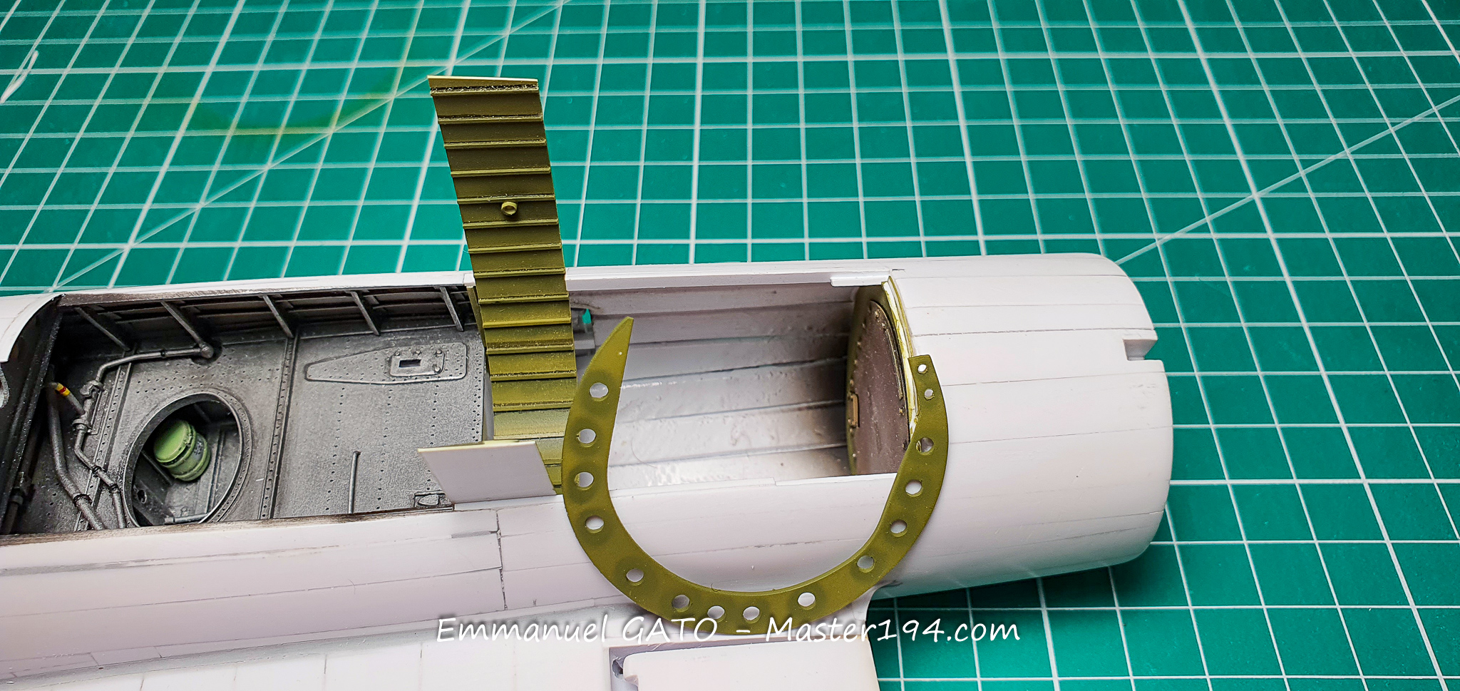
I then returned to the wheel wells. After building the frames and stringers, I sliced the assembly into sections and fed each piece in separately, taking advantage of the plastic’s flexibility—a sort of “multi-layered hamburger technique.” It’s not perfect, but I’ll settle for it!
Still left to do are the landing gear doors, the engine exhausts—28 of them if my count is right—and a bit of touch-up work at the rear of the engine cowlings.
The engine section with the cowlings held in place by rods anchored to the cylinders. Below, you can make out the bulging belly of the oil cooler.
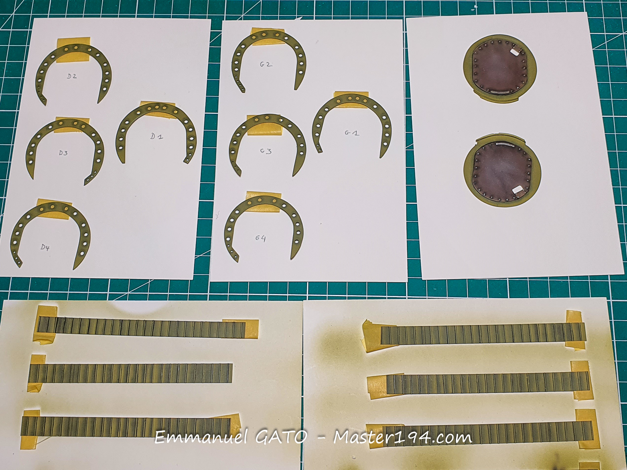
The various parts making up the wheel well: the frames and stringers are secured to 0.25 mm styrene sheet using Tamiya Extra Thin cement (green cap), before painting and slicing into sections.
The installation technique: the frames are inserted at an angle, then wedged slightly into position against the walls. A row of stringers is then slipped in between two frames.
The finished work. I added a few drops of glue just to be safe, even though the tight fits would almost allow the whole assembly to hold together purely by friction. I haven’t installed the final internal details yet: there is still sanding left to do, and I’d rather avoid turning those tiny parts into dust traps or fragile items that would have to be remade.
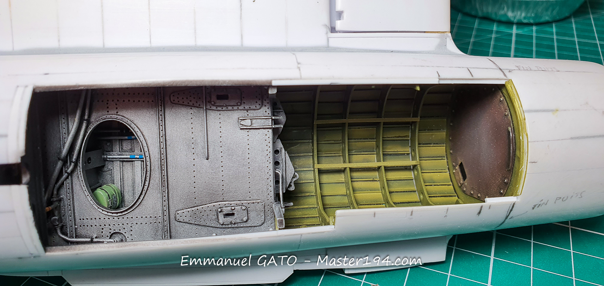
Someone asked me if the offset of the stringers between the frames was intentional. Of course not! On this first wheel well, I got caught out during gluing: when pressing the part down to the bottom, it shifted slightly. I was much more careful on the second one. But once the bay is closed up, very little of it remains visible, especially once the doors and landing gear are in place.
Wings, control surfaces, and surface effects
After several weeks of work, the wings are coming along nicely. At this scale, all problems are multiplied—and I’m not even talking about the tiny rivet holes that have to be done one by one…
The joint between the wing and the center wing box represents the first major challenge. The fit already satisfies me, even though the clamping screw running through the wing hasn’t been tightened down yet. Once under tension, the joint becomes practically invisible. First objective achieved!
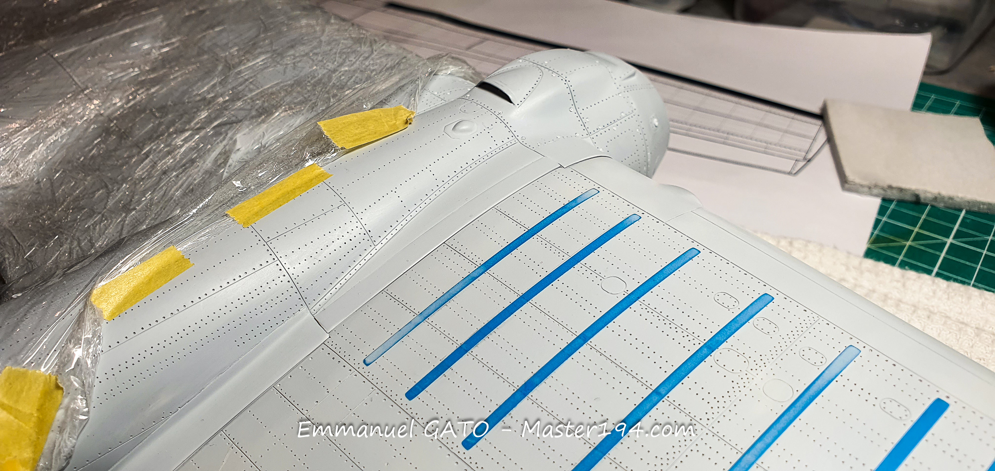
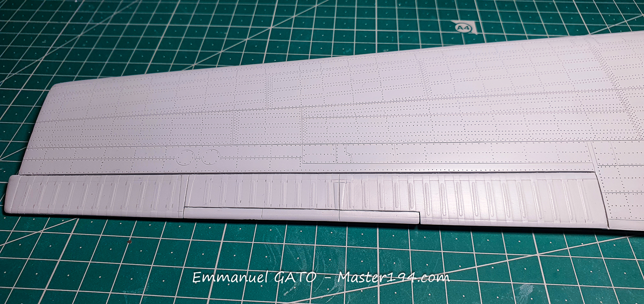
The second challenge concerns the control surfaces, which are fabric-covered on this aircraft. To replicate this effect, I used automotive primer sprayed through the airbrush, building up the layers that make up the fabric texture. The “rib tapes” (le lardage), which represent the raised reinforcement strips, are cut using a Silhouette cutter by transferring the dimensions of each strip.
Masking with Tamiya tape prior to spraying the primer meant to simulate the fabric rib tapes.
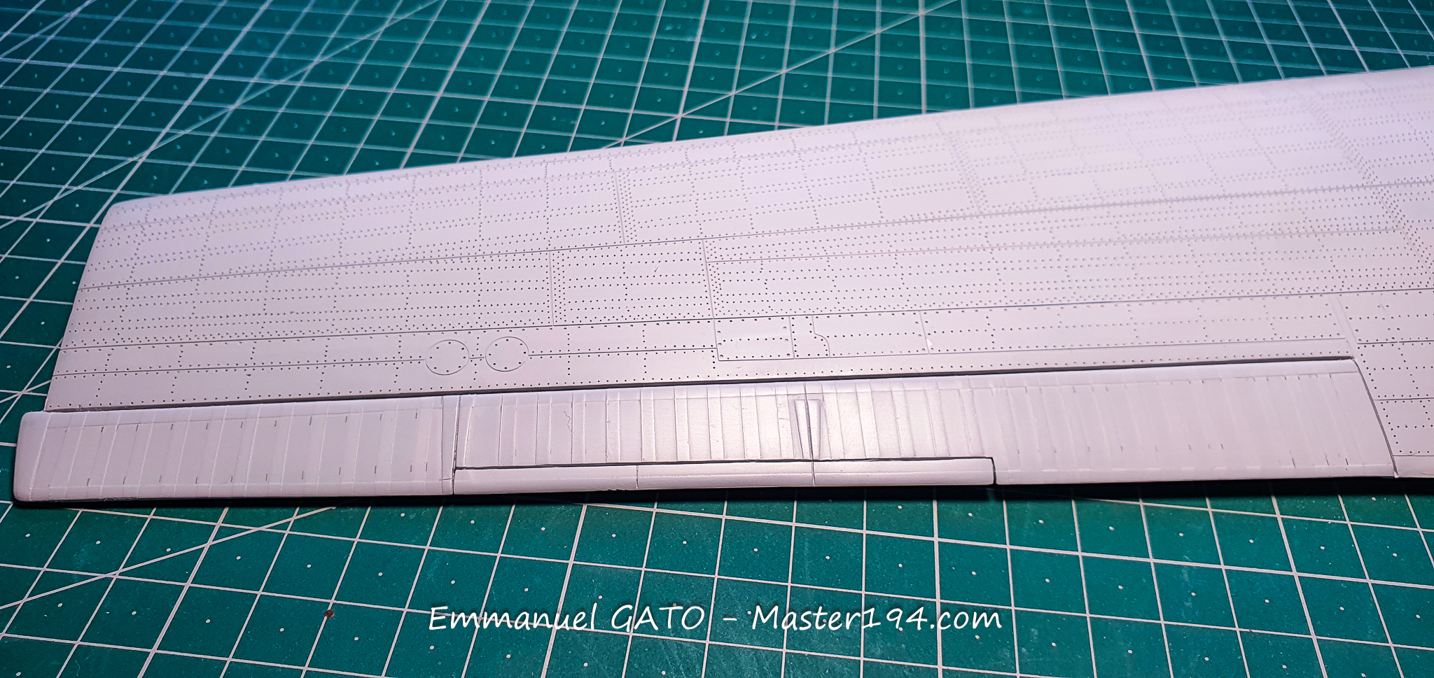
The result after unmasking.
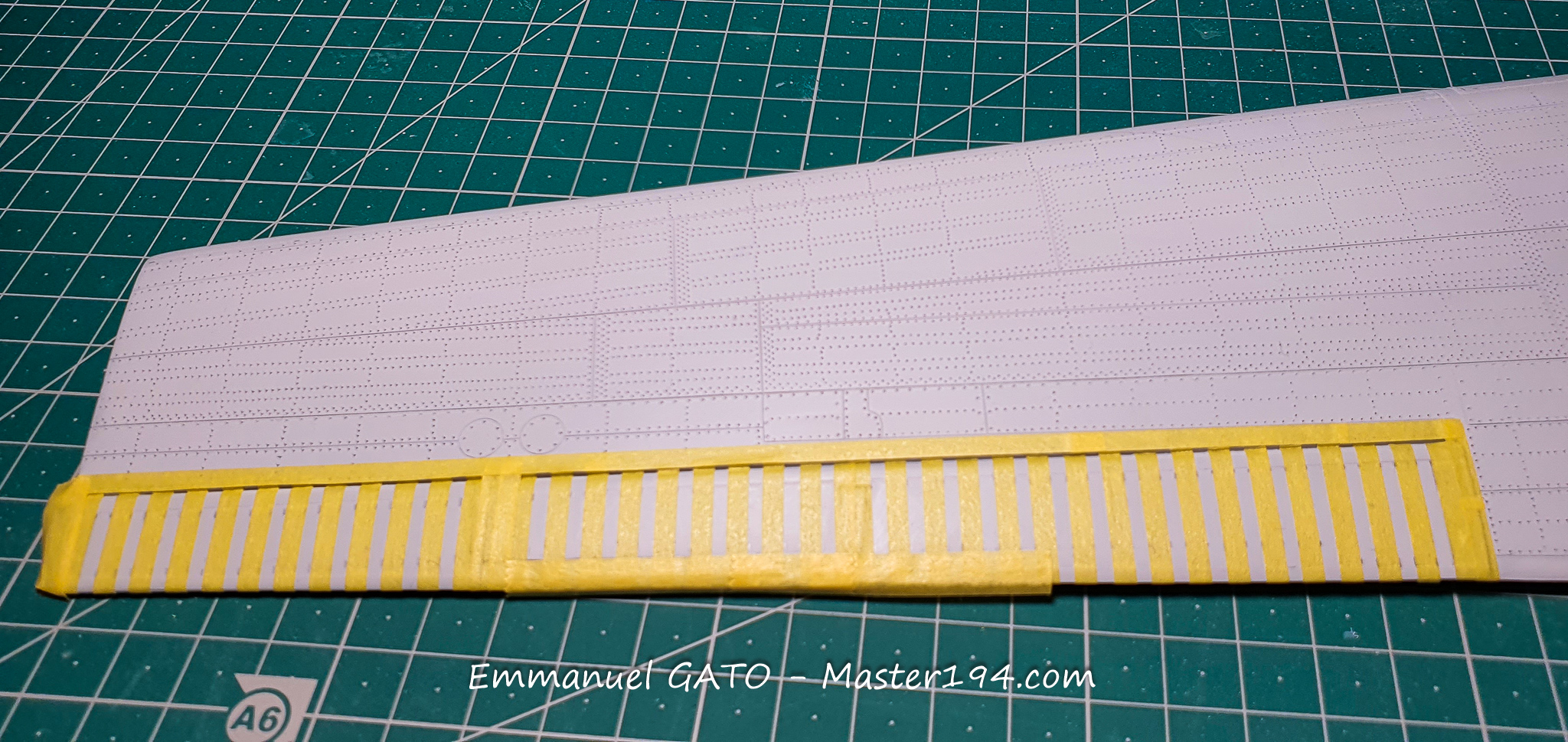
The various dimensions are plotted on the wing, then cut out using the Silhouette.
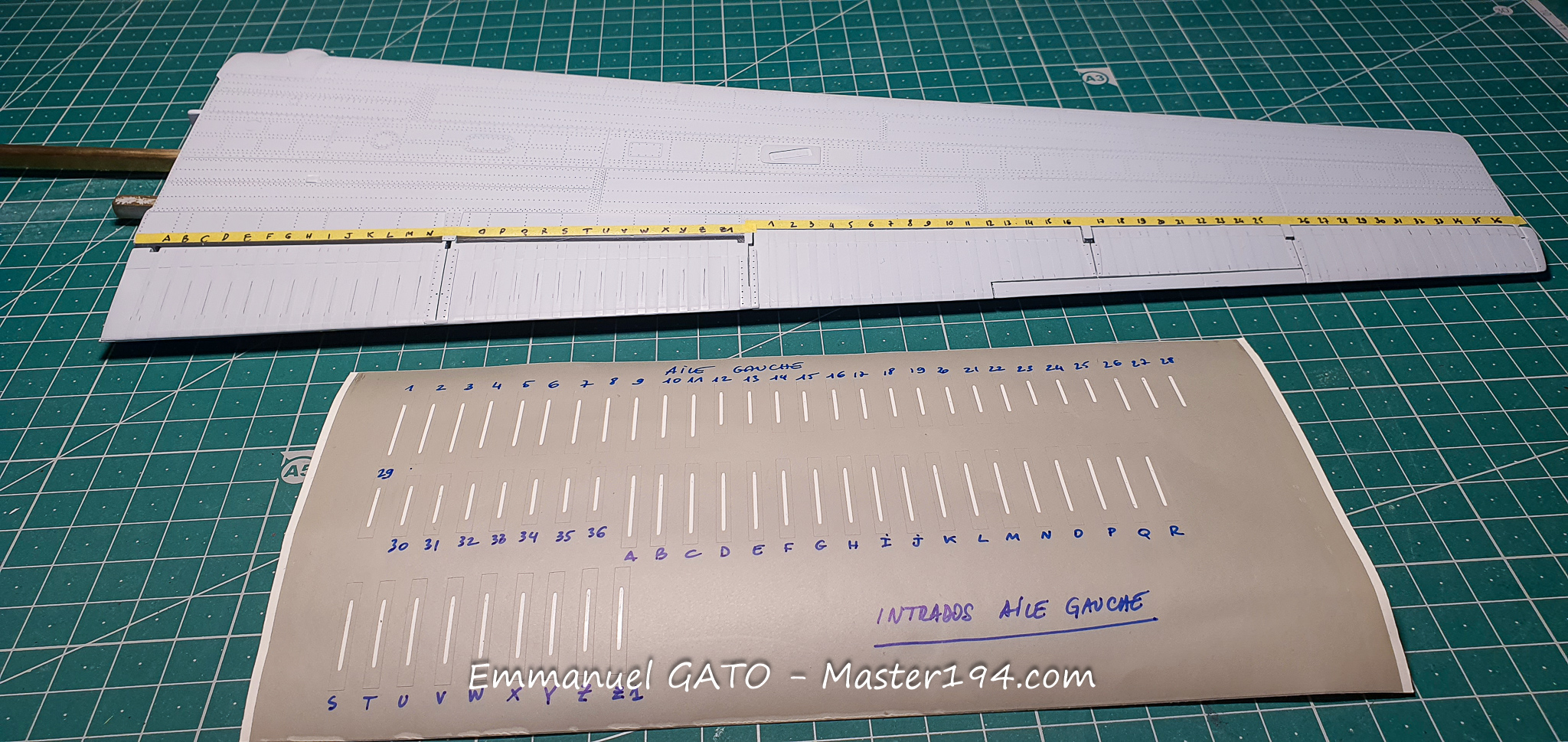
The final result after the various stages.
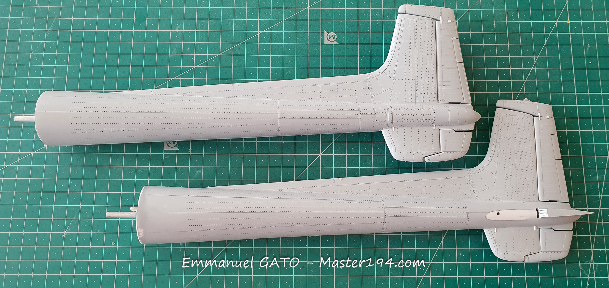
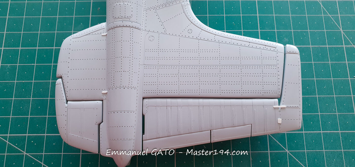
The Noratlas tail booms and control surfaces, including the elevators, are now practically complete. A few details are still missing, such as the control horn linkages and other small parts that I prefer to make only at the very end, given the risk of breaking them during repeated handling.
I am also continuing work on the panel lap joints and fabric effects. All the aircraft’s control surfaces are fabric-covered rather than metal-skinned. The method used on the wings has been refined as the build progressed. It still relies on two main elements: dope (cellulose sanding sealer) and masking. Above all, it takes a great deal of patience, as the masking process is very time-consuming.
The Silhouette cutter is very handy for reproducing the exact same mask multiple times. The primer is then sprayed on with the airbrush—thinned enough to atomize properly, yet thick enough to build up a tangible layer of texture.
The tail booms of the real aircraft are made of overlapping riveted metal sheets. I therefore used this same technique to replicate the look of this rather rugged construction. The close-up photos highlight a few unsightly specks of dust that will obviously need to be cleaned up before final painting.
The hardest part of such a long-term project is staying the course. I will soon permanently assemble the main components: the center wing box, outer wings, tail booms, and horizontal stabilizer. Only then will I start on the fuselage, which will be another tour de force.
This period also coincides with my retirement and my move to Provence. My goal is to finish the model before this transition, as the moving process is likely to limit my availability for scale modeling for a while.