 by
Painting and interior detailing
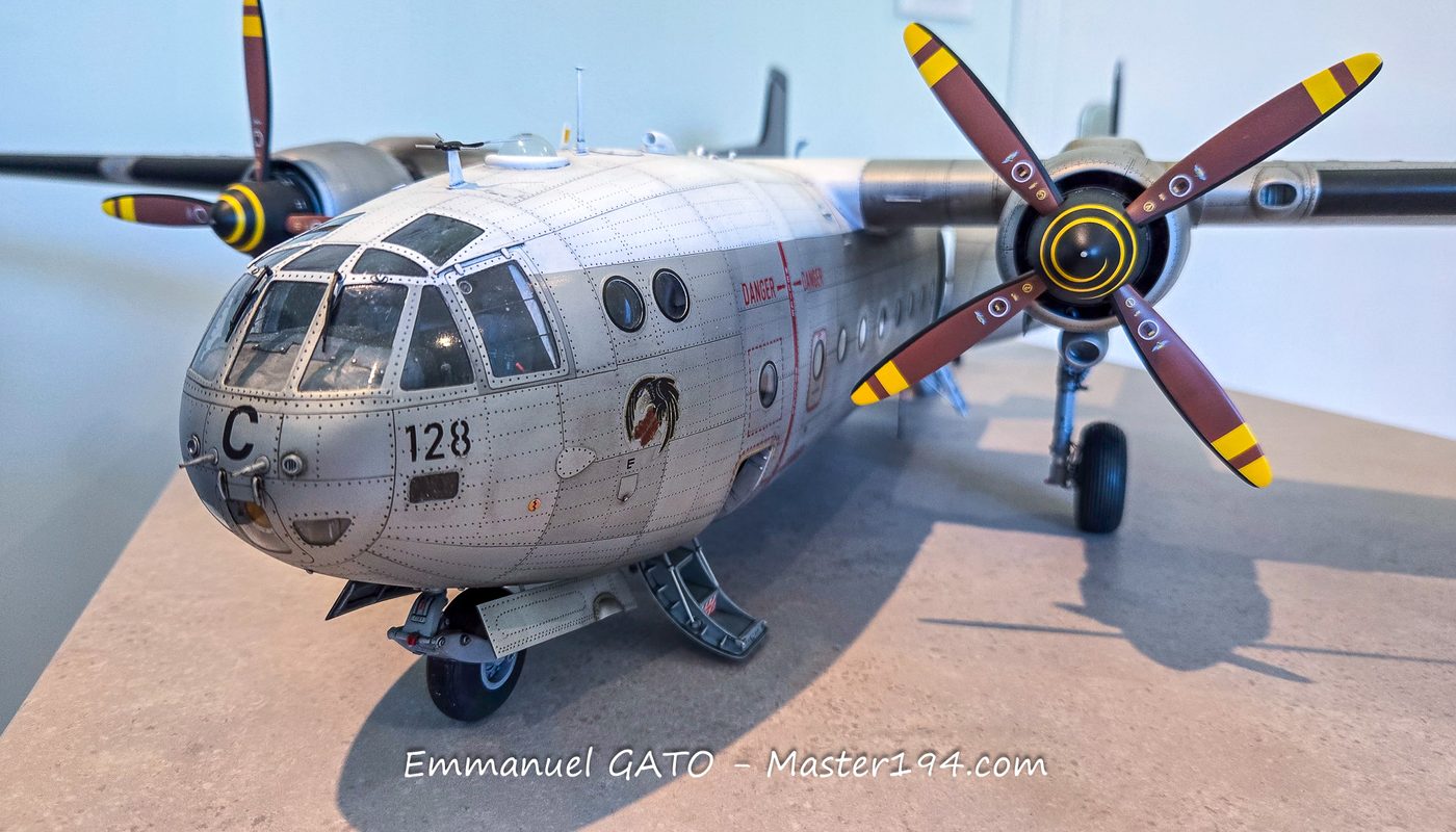
I have finally started painting the model. After more than two years of construction, the project is beginning to take on its definitive look.
However, this long build time has one drawback: you no longer always remember where every little box or detail goes. Fortunately, along the way, I built in numerous indexing pins and alignment keys that force each part into its unique position. Phew!
AD
A few specifics on the products used:
- the cabin floor chipping effect was done using the dedicated Vallejo chipping medium;
- the instrument decals come from ANYZ or AIRSCALE;
- the small informational placards are also provided by these brands;
- after applying DACO decal setting solution, I use AK’s “Precision Antishine,” which allows them to completely blend into the background. I highly recommend it;
- all other buttons and controls are painted by hand.
Here is the current state of the model. The light at the end of the tunnel is starting to show, even though there’s still quite a bit of work left.
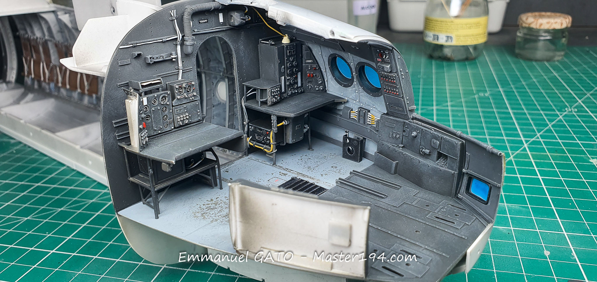
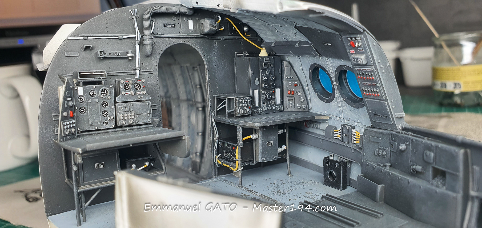
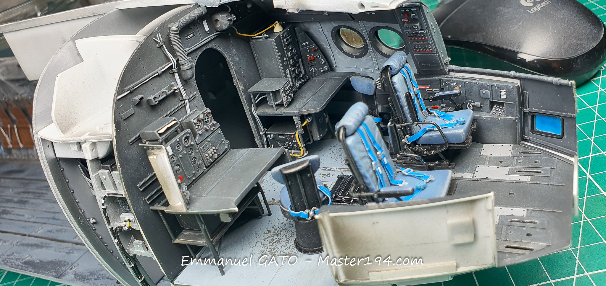
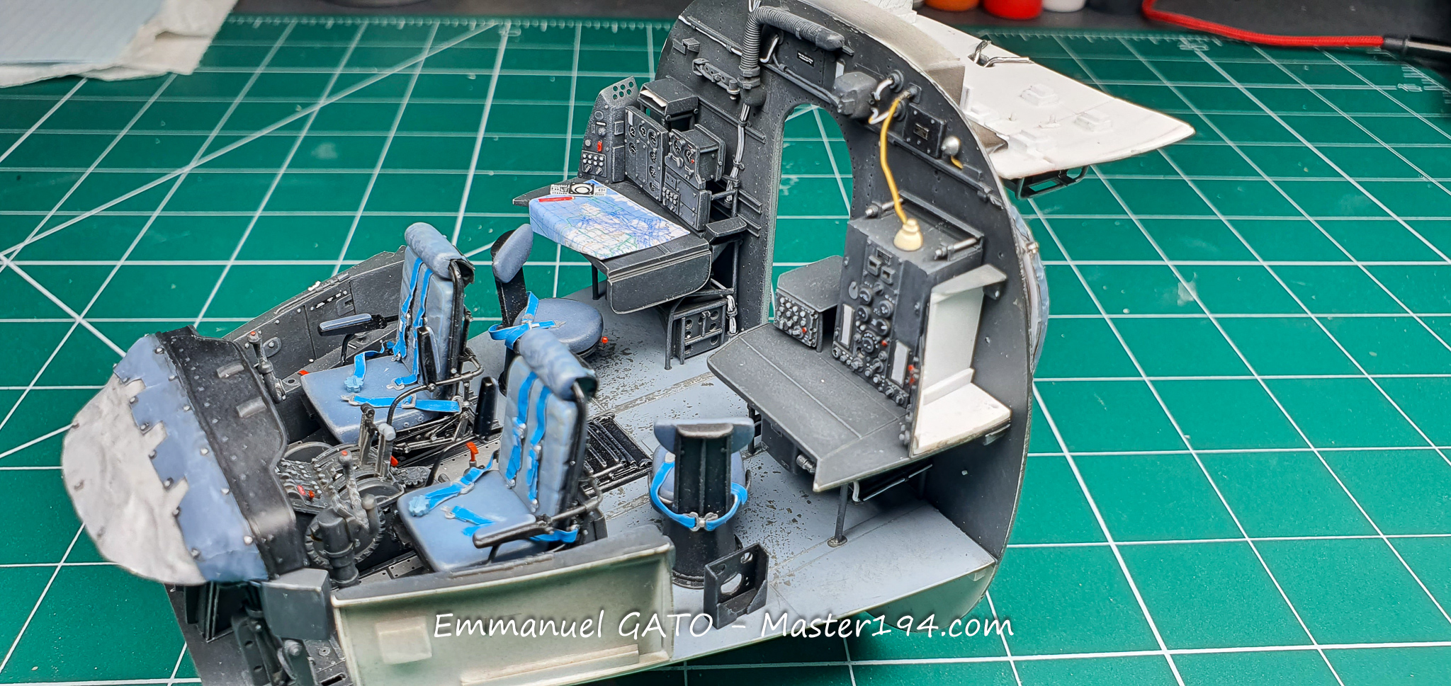
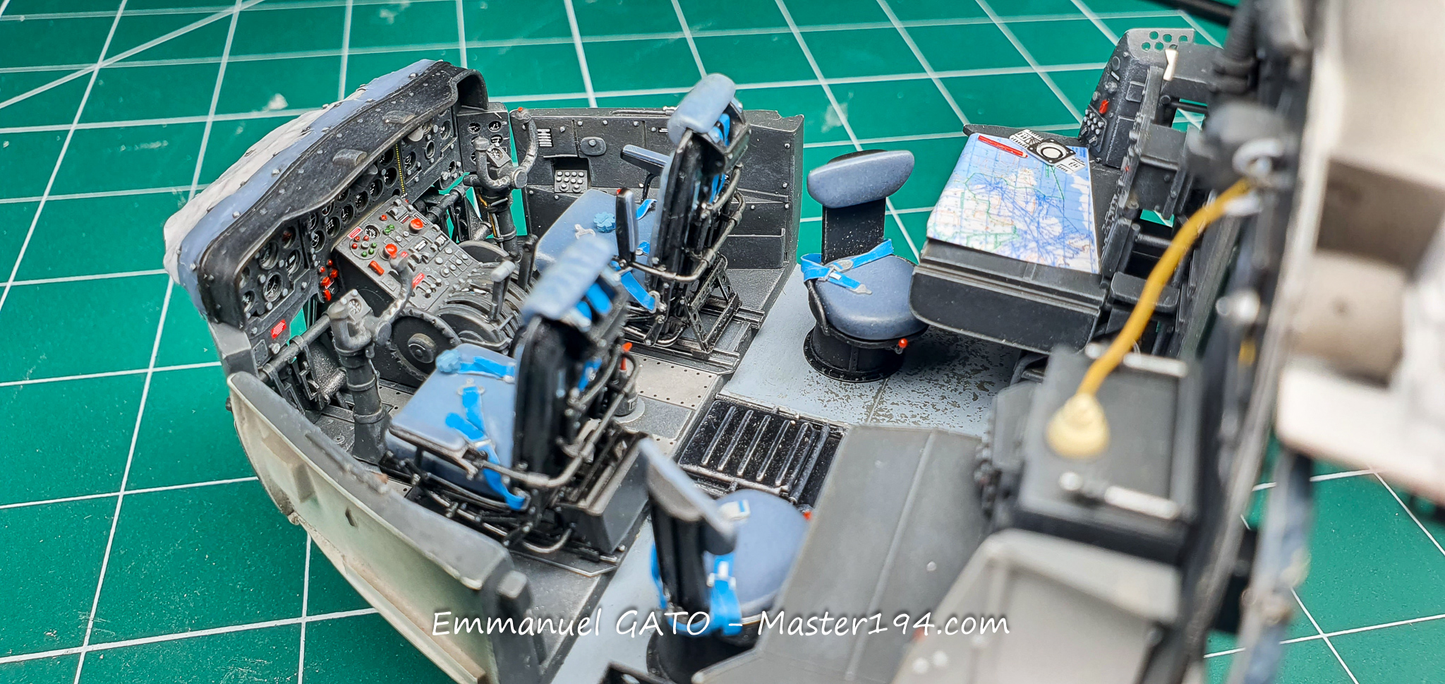
To take stock of the interior, here are three additional views. Since the last post, I have added the radio operator’s, navigator’s, and pilots’ seats. You can easily spot the difference in comfort between the front and rear seating.
Not being able to find seatbelt buckles in the correct scale, I cut them out from thin styrene sheet and threaded the belts through them, just like on the real aircraft.
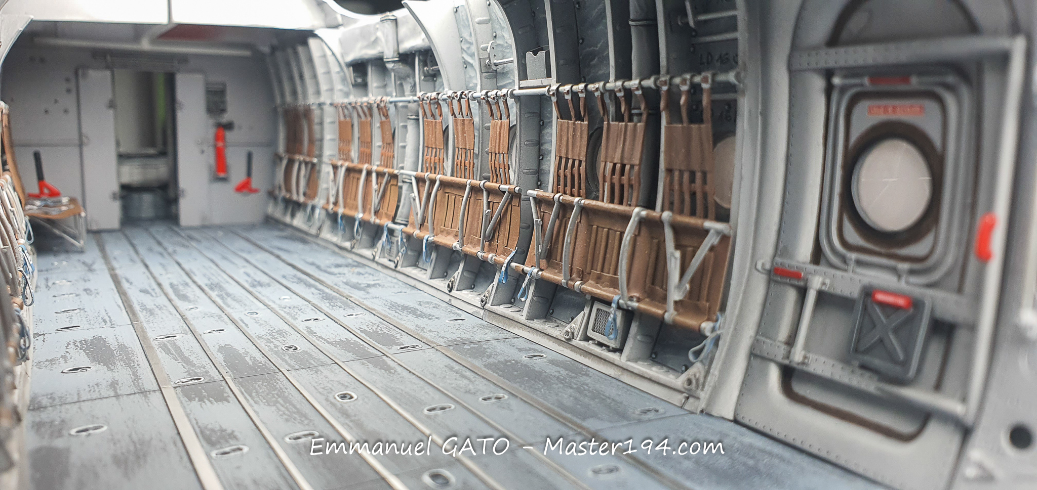
This view shows the seats and the interior layout.
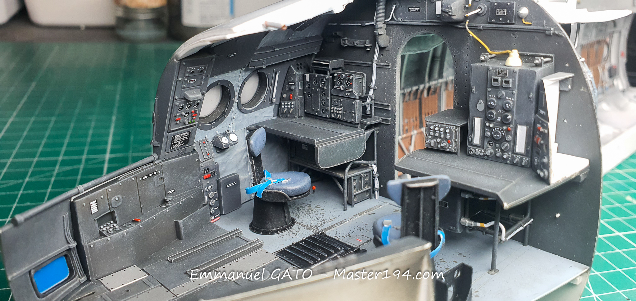
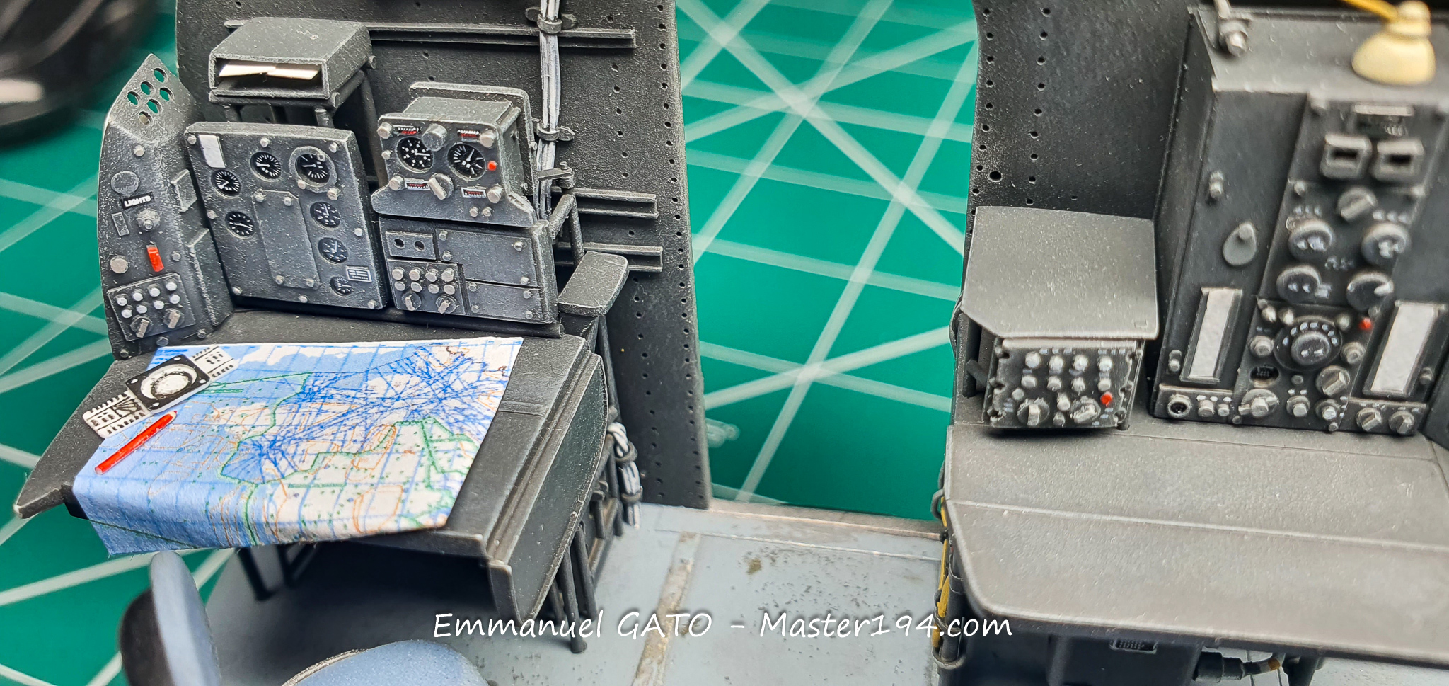
This photograph highlights the bulkhead located right behind the cockpit. The decals come from the original 1/32 sheet produced by Chris Queyroi (from FFSMC productions). You can clearly see the massive amount of avionics packed into this decidedly crowded companionway.
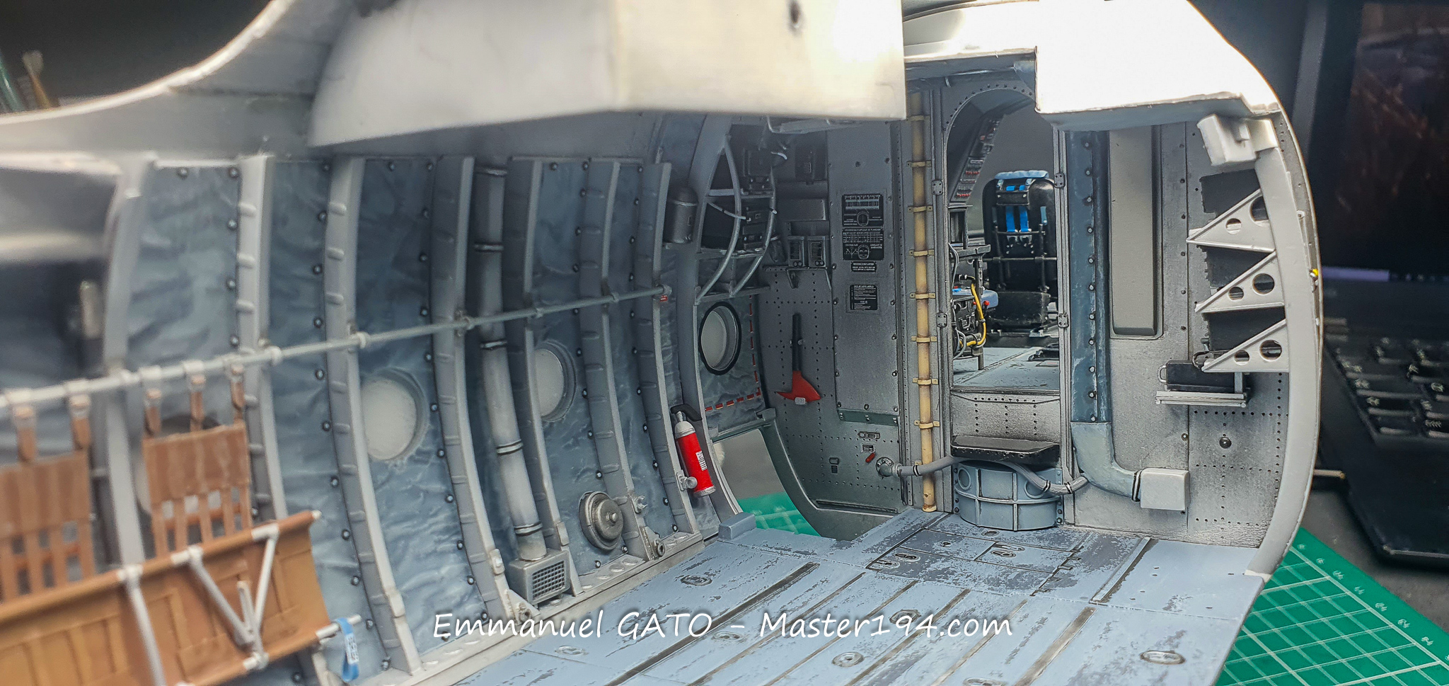
Here is the forward cargo bulkhead with its various items of equipment: emergency axes and fire extinguishers, which can be found scattered all over the aircraft. This section will be particularly visible since the rear fuselage halves will be displayed open.
The floor wear was replicated using Vallejo chipping medium. A few details are still missing, notably an open bench seat, deployed stretchers, and the tirefort—the winch used to hoist cargo into the aircraft. In the case of my model, it will be rigged up for loading a Mirage III engine.
This other view of the flight deck focuses on the navigator’s station. Normally, a blackout curtain sits between the co-pilot’s seat and the navigator’s station. I left it out because it would have hidden a good portion of the work. Let’s call it a modeler’s license…
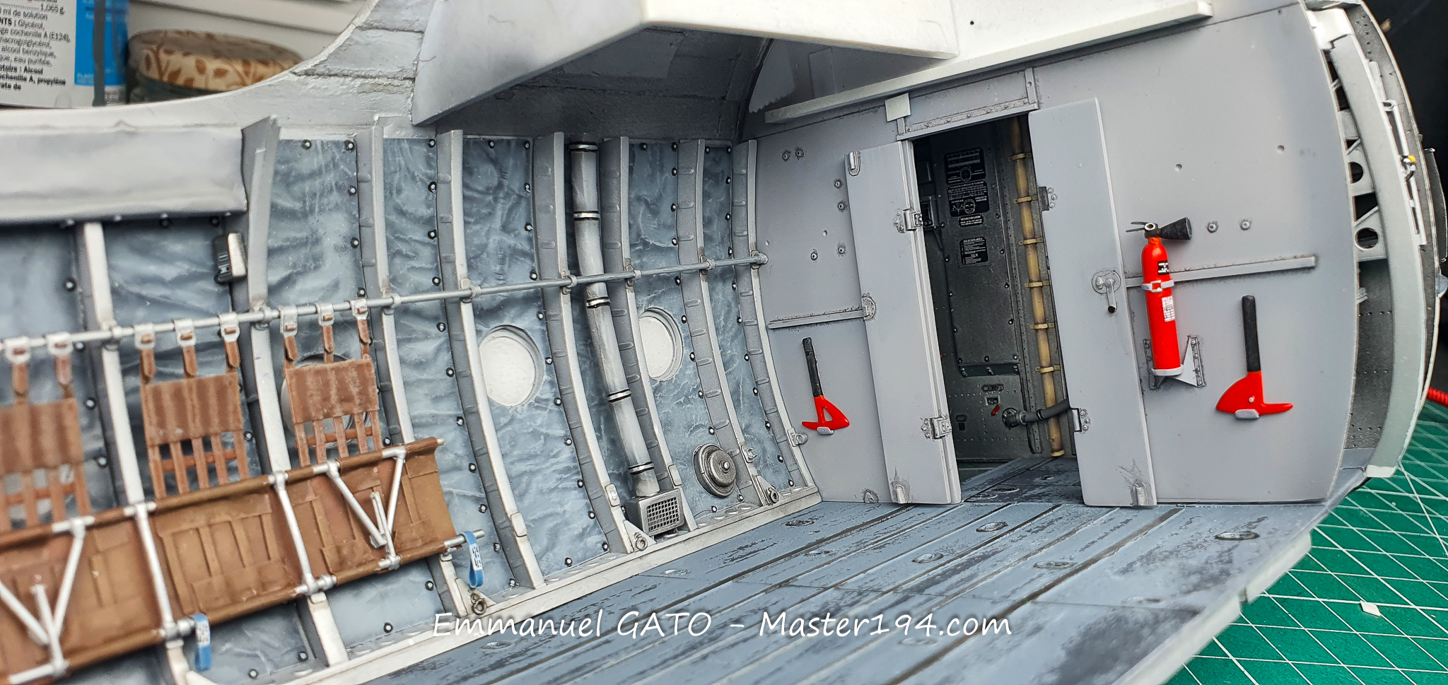
The forward left section with one of the troop bench seats deployed. Above it is a stretcher, which was actually used as a shelf for the crew’s personal gear.
On the floor, you can make out the tirefort—the hand winch used to pull cargo up the access ramps. For this build, it will be used to load an aero engine.
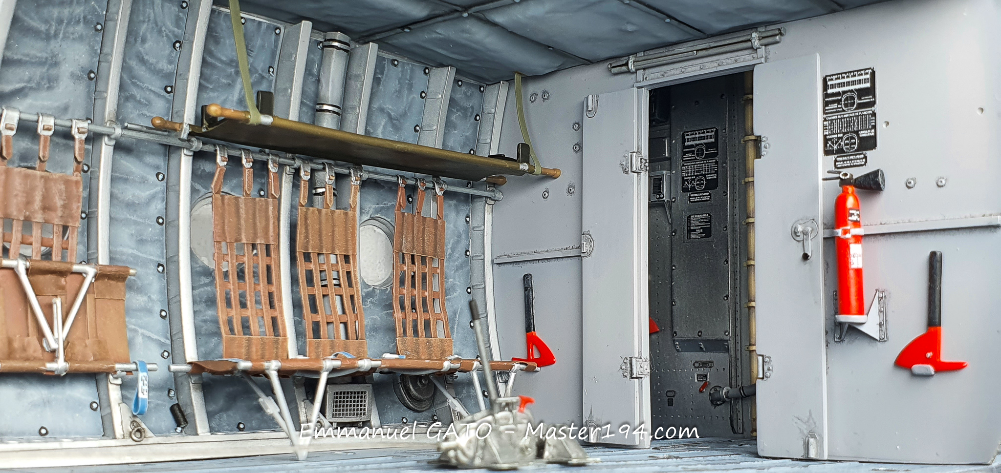
A general view of the cargo hold. The photos taken with my phone aren’t extraordinary, particularly regarding the depth of field, but they still give a good sense of the overall atmosphere. Be indulgent!
Before closing up the fuselage, I am taking advantage of these final “open-air” views to show the cockpit. I added a few extra details purely for my own enjoyment, such as a navigation map that will just barely be guessed at through the front side windows. On the other hand, I skipped certain accessories, like headsets, which would have been hidden by the seats anyway.
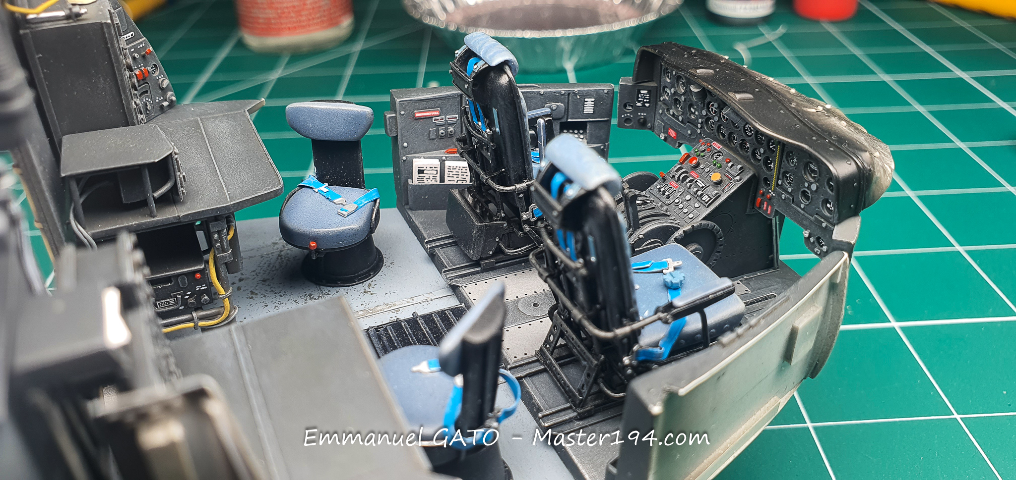
The instrument decals, which I tried to make as close to reality as possible, come from ANYZ. They are remarkable, and I highly recommend them.
Final airframe assembly and detachable wings
Construction is progressing at its own pace—slow but steady—and is nearing completion. The center wing box has been securely mounted onto the fuselage and blended into the assembly. This involves filling and sanding, replicating overlapping skin panels, and, of course, riveting.
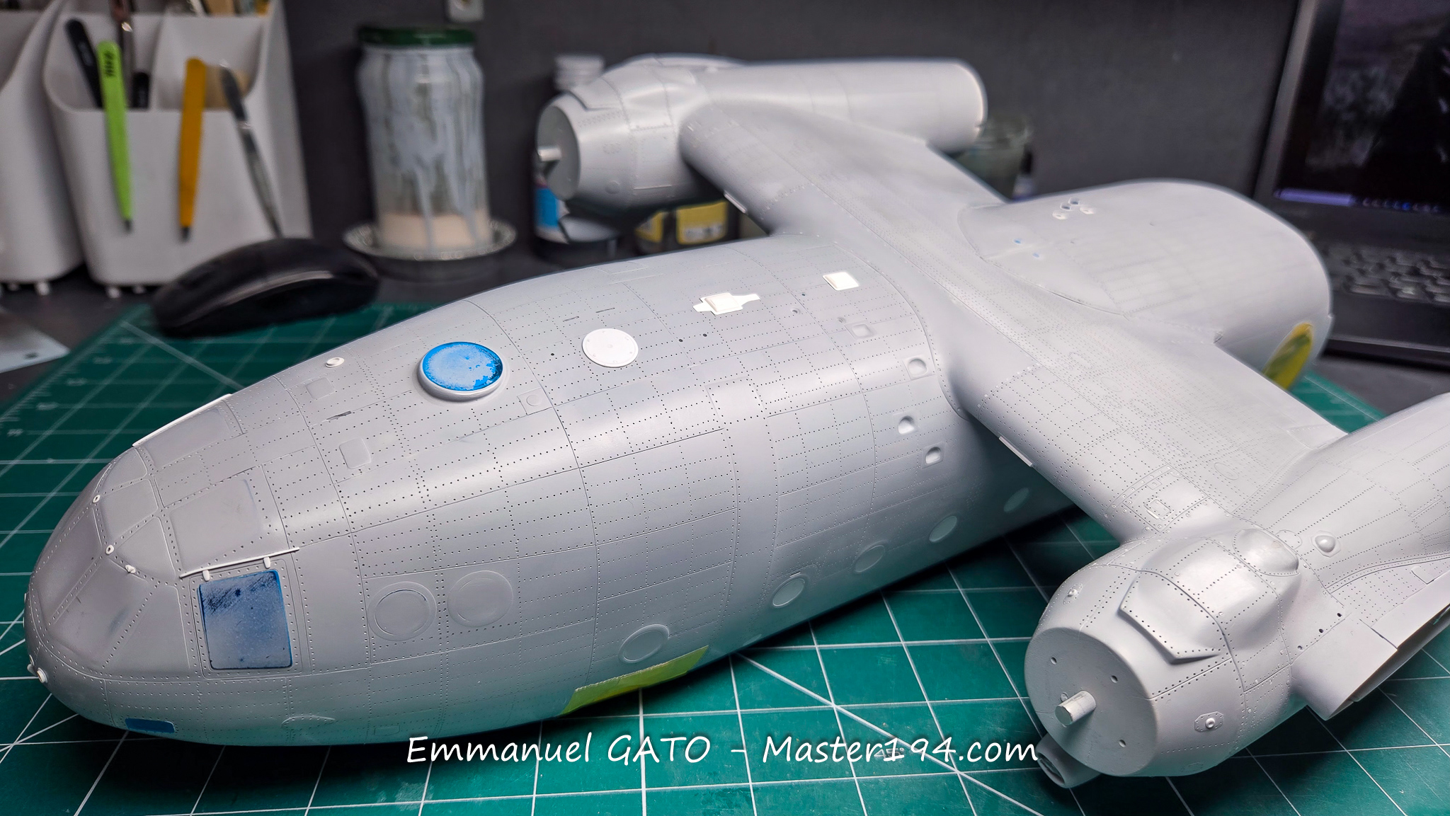
Another aspect that gave me a few cold sweats was the detachable wing mounting system. As a reminder, the Noratlas in 1/32 scale has a one-meter wingspan. Two years after designing the mechanism, I can finally test-fit the wings and confirm that the principle still works as intended.
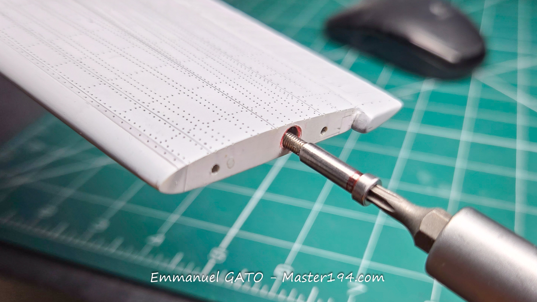
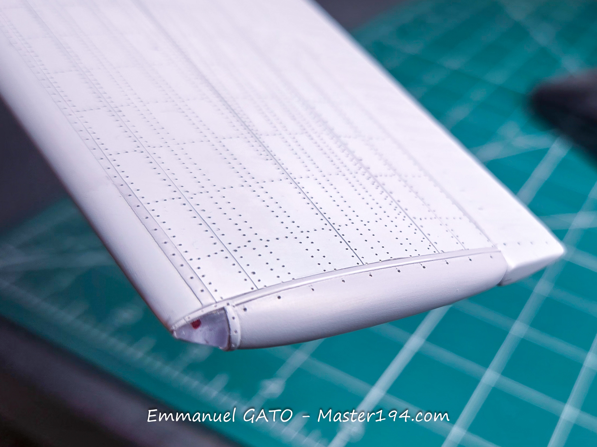
A threaded rod runs through the wing and terminates in a hex-head screw that allows for gentle tightening. The mechanism is concealed at the wingtip by a partially hollowed-out tip cap that restores the airfoil profile.tuer le profil.
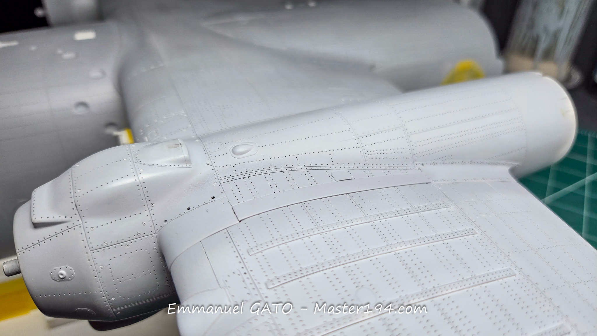
The result satisfies me: the joint between the wing and the wing root located on the tail boom is virtually invisible when you don’t know it’s there. That is precisely what I was aiming for.
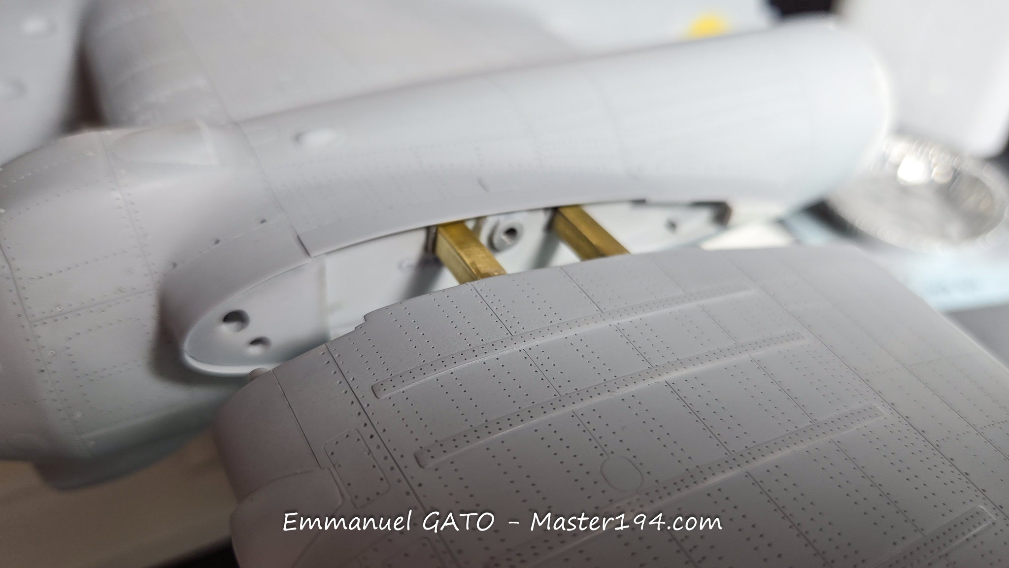
The wing root attachment: a threaded tube traps the rod passing through the wing. You can also make out the two square tubes that form the spars essential for aligning and supporting the wing.
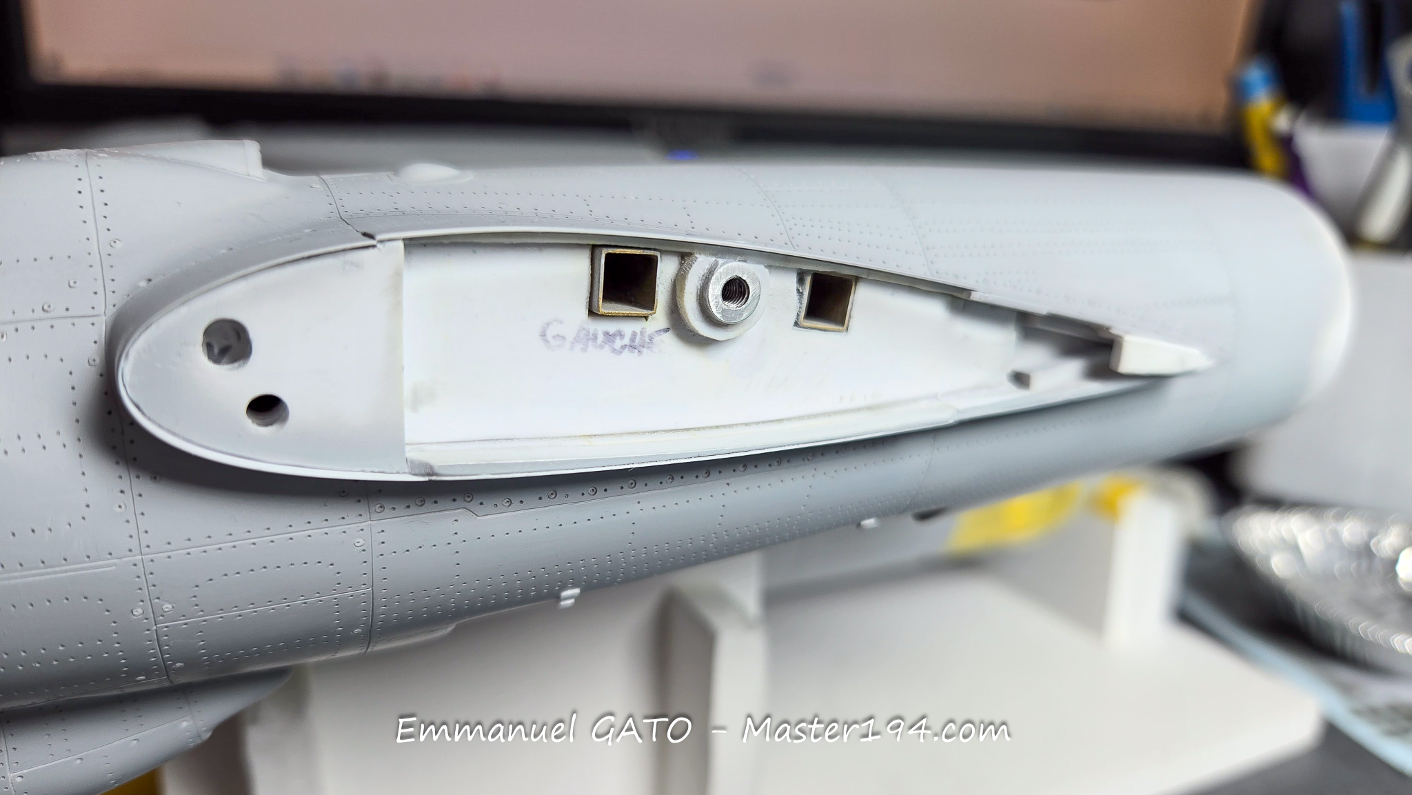
The guided spars.
Tightening the rod.
The mechanism is concealed by the wingtip. I won’t lie to you—all of this requires very meticulous adjustments. You must not hesitate to remake a part when it lacks precision. A few frustrating evenings guaranteed!
The work is complete. The joint is masked by plastic strips that replicate panels present on the real aircraft, which also serve an aerodynamic function for this junction.
The next step is to install the two open clamshell doors and their mounting system. I don’t know yet whether I’ll make them detachable for easy transport or glue them permanently. Afterward, it will remain to attach the tail booms equipped with the horizontal stabilizer. All the major parts are fabricated and simply waiting to be put in place.
Before heading off on vacation for a few days, here is the rear section of the cargo hold with both clamshell doors open. It already gives a good idea of the final look, even though this area isn’t completely finished yet.
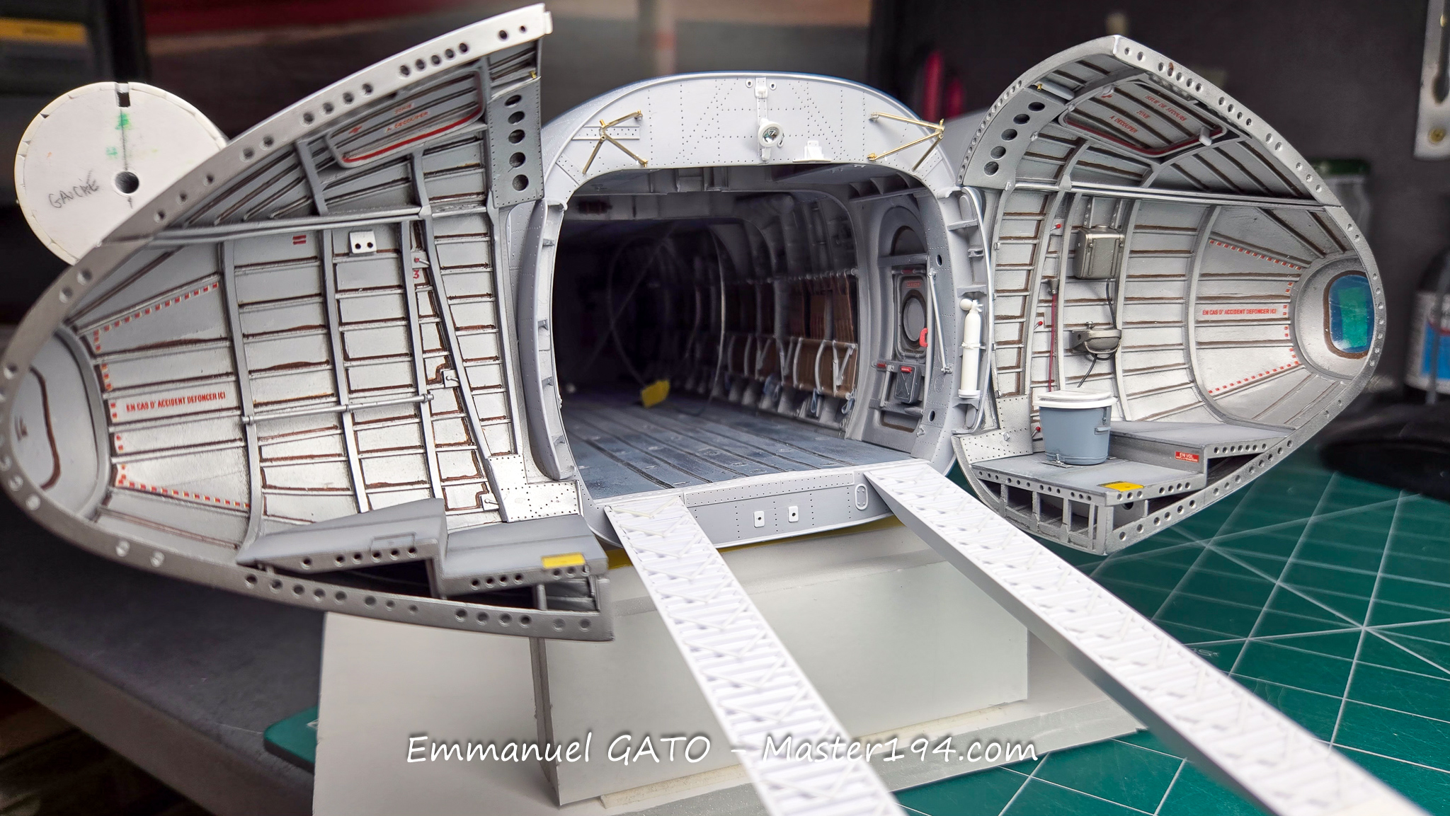
One specific detail concerns the rear ramps. In particular, they must help support the model on its nose landing gear without adding too much weight up front. After several balancing tests, I had to change my strategy: despite adding over 400 grams, the model kept tipping back onto its tail booms. I had to use a bit of imagination.
Thank you for your suggestions and some details on the solutions considered:
- A lead pallet would have helped weight down the nose, but I abandoned this idea after reaching an unreasonable weight. The main risk was weakening the nose wheel attachment. Another drawback: it would have cluttered the cargo hold and compromised the scene I want to depict, which is the loading of a Mirage III engine. When transporting an engine, the Noratlas really didn’t have room for much else.
- The two auxiliary struts, known as chambrières, will be in place, but they are too fragile to support the model’s weight on their own.
- The ramps are built around two 2 mm diameter brass tubes that slide into two other tubes of the same diameter, securely glued into the fuselage. They are therefore very sturdy. I won’t be able to verify their effectiveness until the landing gear is installed, but I’m feeling rather confident.
The Nord is moving forward a bit more slowly right now due to renovation work and a move. I still tinker whenever possible.
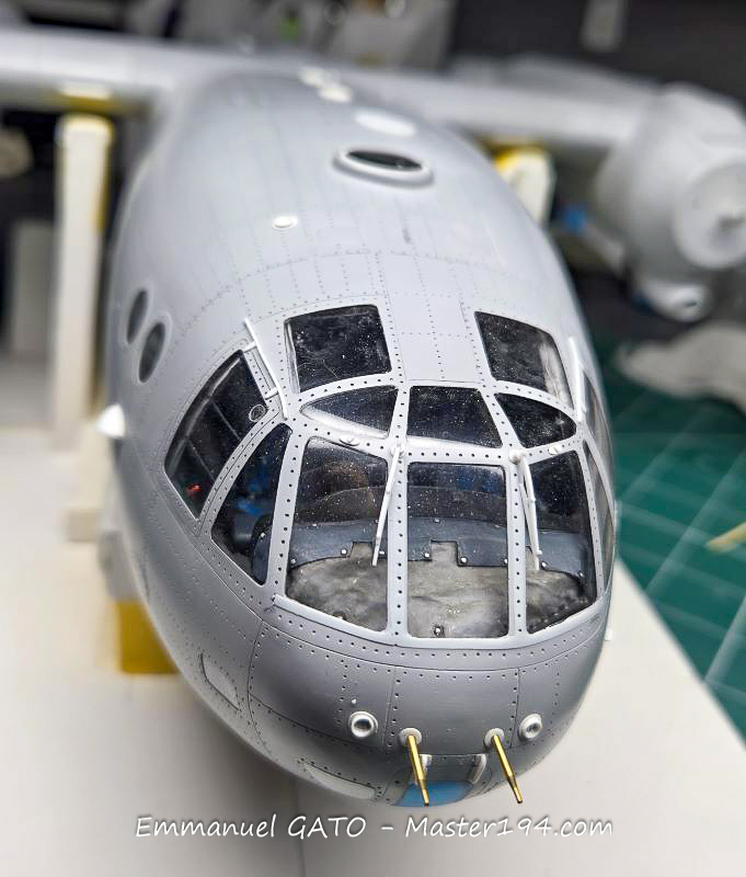
Let’s start with the nose cone. It won’t hide much given the size of the glazed areas, which were vacuum-formed “in-house.” Both Pitot tubes are made of brass and the wipers are plastic.
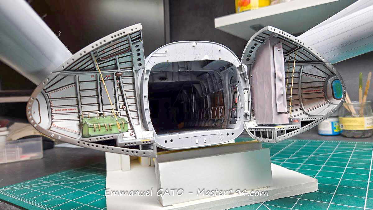
The half-shells have been fitted out. Aside from a few additional details, they are ready to be installed.
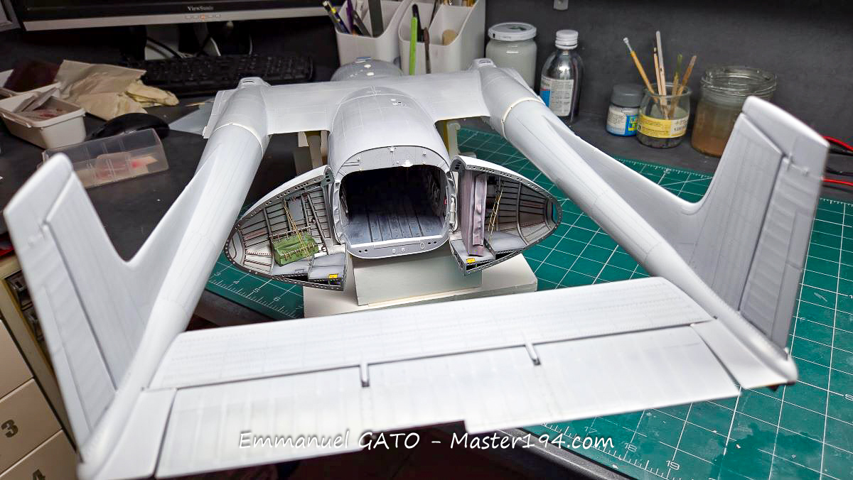
The guiding mechanism for opening the doors doesn’t appear in the photograph. It consists of small tubes and serves to limit their travel range. We’ll come back to that later.
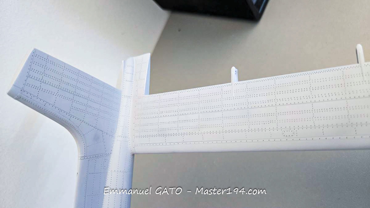
Both tail booms have been glued in place, patiently filled, and then blended in through riveting. This particularly crucial step is finally finished!
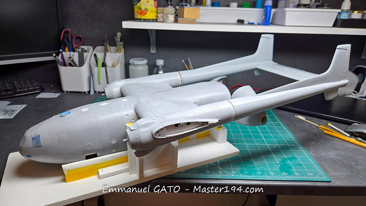
Here is the result after a few hours of making “little holes”…
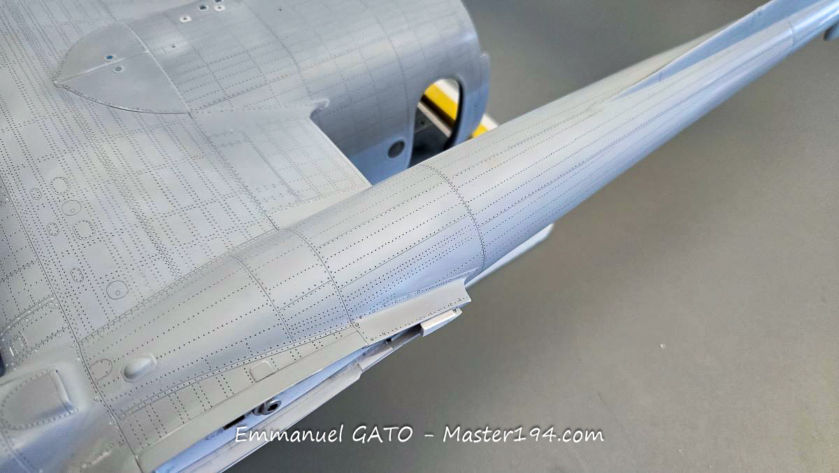
The horizontal stabilizer underwent the same treatment. It too was integrated into the airframe using a rather complex fairing fillet. That work is now complete. The rudders and elevators are not yet installed in this view.